Method and system for sequestering carbon emissions from a combustor/boiler

a carbon emission and combustor technology, applied in the direction of emission prevention, separation processes, lighting and heating apparatus, etc., can solve the problems of not making a significant contribution to reducing atmospheric concentrations of cosub>2 /sub>at a reasonable cost, and the cost of implementation is relatively high

Inactive Publication Date: 2008-10-21
ECO TECH LLC
View PDF17 Cites 85 Cited by
  • Summary
  • Abstract
  • Description
  • Claims
  • Application Information

AI Technical Summary

Benefits of technology

[0017]It is an object of the present invention to provide a method and system that enables retrofitting any conventional combustion plant emitting CO2-laden combustion or flue gases to sequester carbon emissions.

Problems solved by technology

All of these strategies are extremely expensive and extremely risky in the event of natural disasters such as earthquakes, tsunamis, and the like.
However, the amount of CO2 emitted into the atmosphere dwarfs the market for commercial usage, so these and similar approaches would not make a significant contribution to reducing atmospheric concentrations of CO2 at a reasonable cost.
Although this approach is valid, the cost to implement is relatively high because of the need for constructing expensive oxygen enrichment facilities.
For example, U.S. Pat. No. 6,205,704 to Schmitz uses photosynthesis to accept flue gas from the combustion of landfill gas, but does not address major utility and industrial power plant emissions.
A high-pressure water stream is used to harvest the bacteria off of the membrane, but the patent does not address the cost of drying the biomass to provide feedstock for products such as fertilizer, alcohols, or power plant fuel.
Because of the large volumes of water used in the harvesting process, this cost could be very high.
One drawback of the Brais system is that the fly ash would likely plug the heat exchanger frequently and make it very difficult to operate reliably with consistent performance.
Also, a commercial system of this type would be entirely dependent on proper performance of the heat exchanger, failure of which could adversely affect power plant availability.
Other drawbacks include the waste of the heat removed from the flue gas by discharging the air cooling medium to atmosphere, the difficulty in pumping the ash-laden slurry through the system without frequent plugging and severe wear to pumps and valves, the likely damage caused to the plant growth in spraying liquid and ash slurry directly thereon, and the likelihood of aquatic algae growth in the greenhouse that could both rob plants of vital CO2 for accelerated growth rates, but also become toxic to the plants themselves.

Method used


Image

  • Method and system for sequestering carbon emissions from a combustor/boiler
  • Method and system for sequestering carbon emissions from a combustor/boiler

Examples


Embodiment Construction

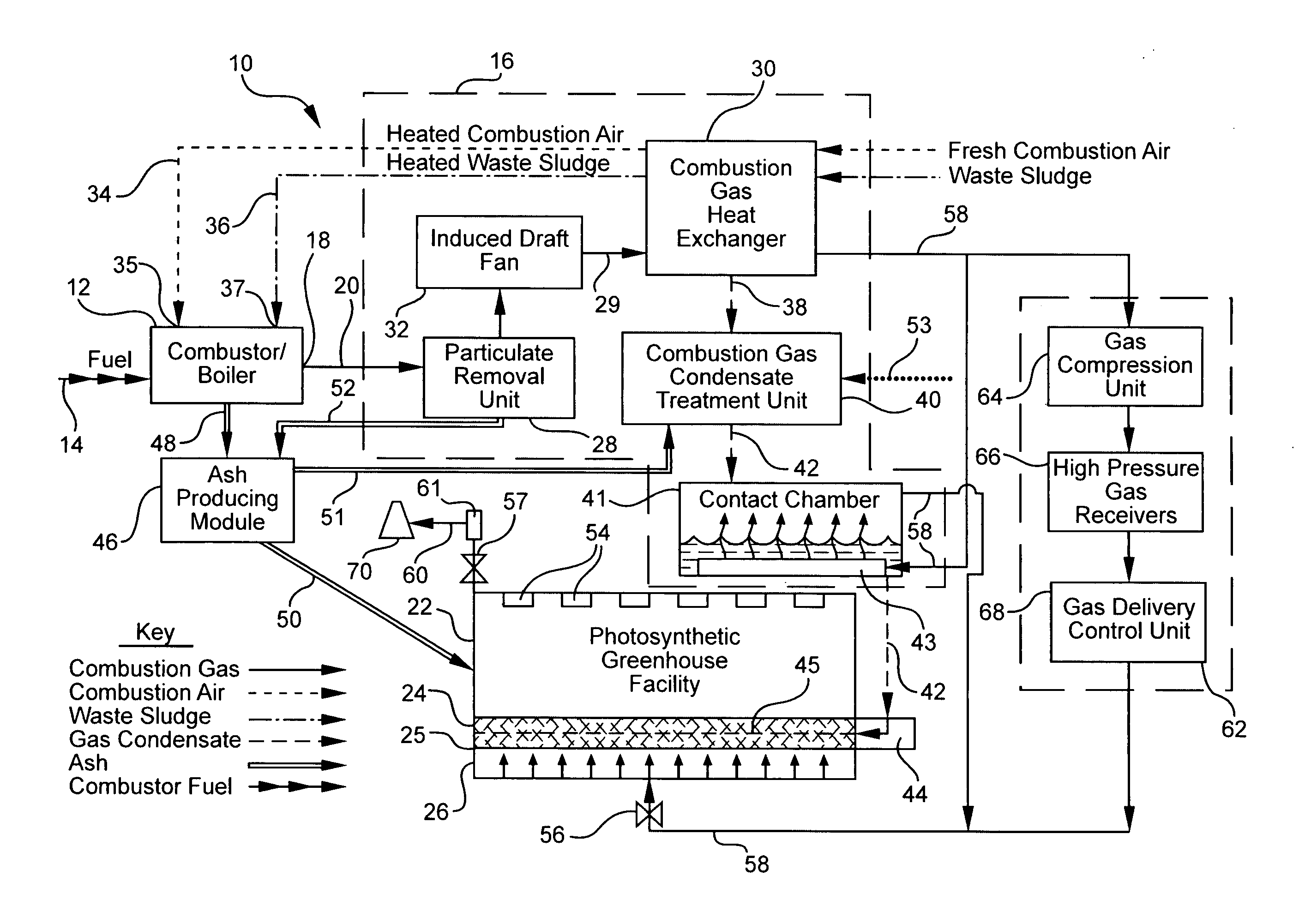
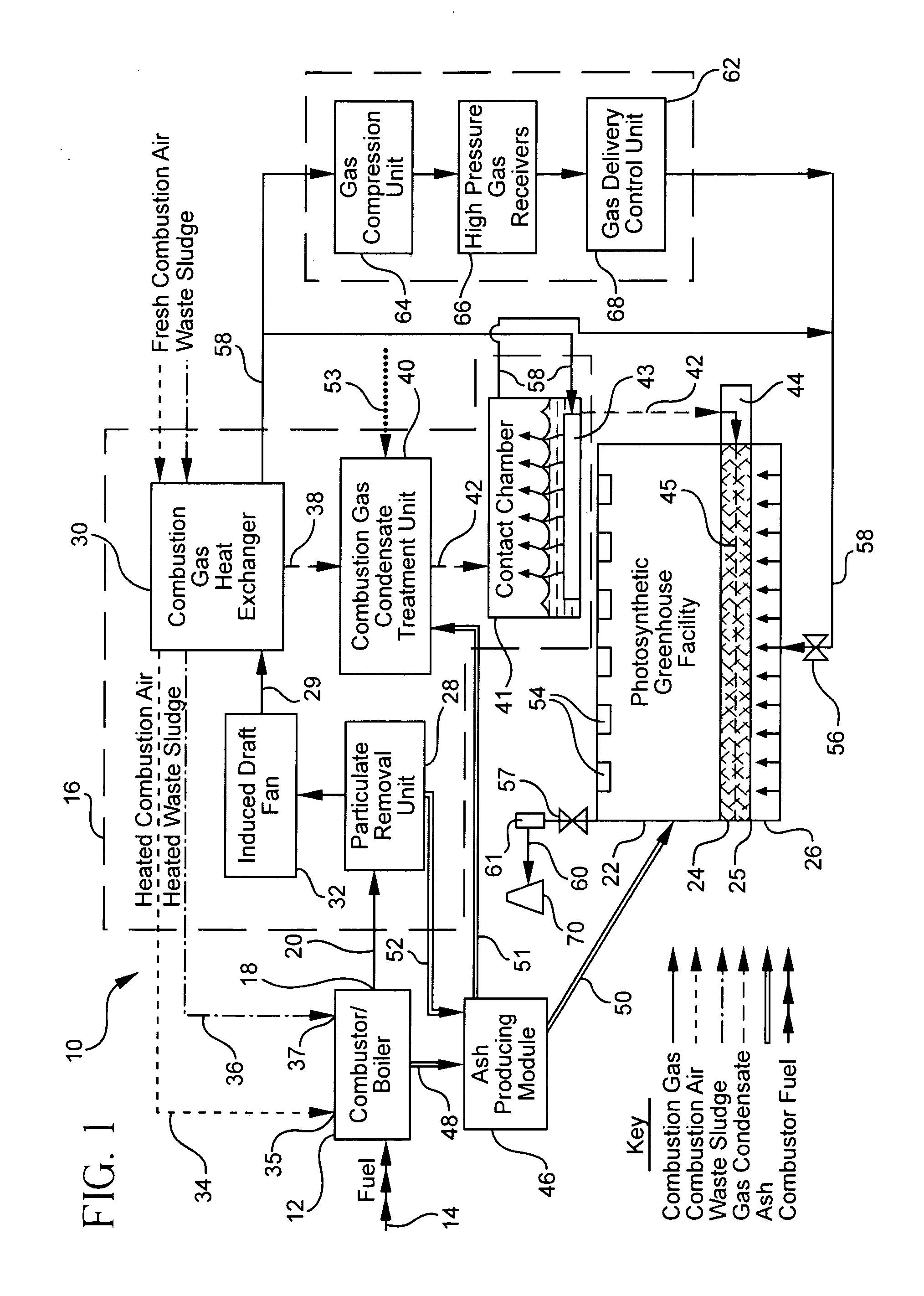
[0044]FIG. 1 illustrates a system 10 for sequestering carbon emission from a combustor / boiler 12 formed in accordance with the present invention. The system 10 is primarily described herein as being adapted to a municipal waste combustor, however, the present invention is intended for retrofit to any existing power plant combustor / boiler 12 using any fuel 14 that emits carbon dioxide (CO2)-laden combustion or flue gas to the atmosphere through an air pollution control system, induced draft fan and exhaust stack. The temperature of the exhaust gas from this type of existing facility is generally maintained well above the dew point to avoid condensation of acid gases and to allow rise of the plume farther into the atmosphere for greater dispersion over a wide area.

[0045]The system 10 according to the present invention generally includes a combustion gas extraction module 16 communicating with an exhaust outlet 18 of a combustor 12 for extracting the carbon dioxide laden combustion or ...


PUM

PropertyMeasurementUnit
electric poweraaaaaaaaaa
concentrationsaaaaaaaaaa
pressureaaaaaaaaaa

Abstract

A system for sequestering carbon emissions from a fuel combustor generally includes a combustion gas extraction module for extracting combustion gas from a fuel combustor and a greenhouse facility for receiving the extracted combustion gas and having at least one vegetation supporting soil bed for absorbing carbon dioxide from the received combustion gas. The extraction module includes a particulate removal unit for removing pollutants from the extracted combustion gas and a heat exchanger in downstream fluid communication with the particulate removal unit for cooling the extracted combustion gas.

Description

CROSS-REFERENCE TO RELATED APPLICATIONS[0001]This application claims the benefit of U.S. Provisional Application No. 60 / 571,431, filed on May 14, 2004.FIELD OF THE INVENTION[0002]The present invention relates generally to improvements in utility and industrial power generation facilities, particularly to those combusting any solid fuel or any fossil fuel in a combustor or boiler, and more particularly to a method and system for sequestering carbon emissions from such combustors or boilers using photosynthesis in an enclosed growth chamber to accelerate the production of biomass and soil amendments in the presence of high concentrations of carbon dioxide.BACKGROUND OF THE INVENTION[0003]Culminating with the Kyoto Treaty to reduce greenhouse gas (GHG) emissions in a worldwide effort to reverse the growing effects of global warming, research has been underway to create methods for achieving this goal. It is widely accepted that one of the greatest contributors to global warming is the ...

Claims


Application Information

Patent Timeline
Patent Type & Authority Patents(United States)
IPC IPC(8): B01D50/00A01G7/02A01G9/18B01D53/84B01D53/85B01J8/00F23J15/00
CPCA01G7/02A01G9/18B01D53/84B01D53/85F23J15/006F23J2215/50F23J2217/10F23J2219/70Y02C10/02Y02A50/20Y02C20/40Y02P60/20
Inventor BEAUMONT, E. LARRY
Owner ECO TECH LLC
Why Eureka
Try Eureka