

Phase-change information recording medium, manufacturing method for the same, sputtering target, method for using the phase-change information recording medium and optical recording apparatus
a technology of information recording medium and manufacturing method, which is applied in the direction of photomechanical equipment, instruments, thermography, etc., can solve the problems of deterioration of storage reliability, lowering of crystallization temperature, and increasing crystallization speed
- Summary
- Abstract
- Description
- Claims
- Application Information
AI Technical Summary
Benefits of technology
Problems solved by technology
Method used
Image

Examples
example 1
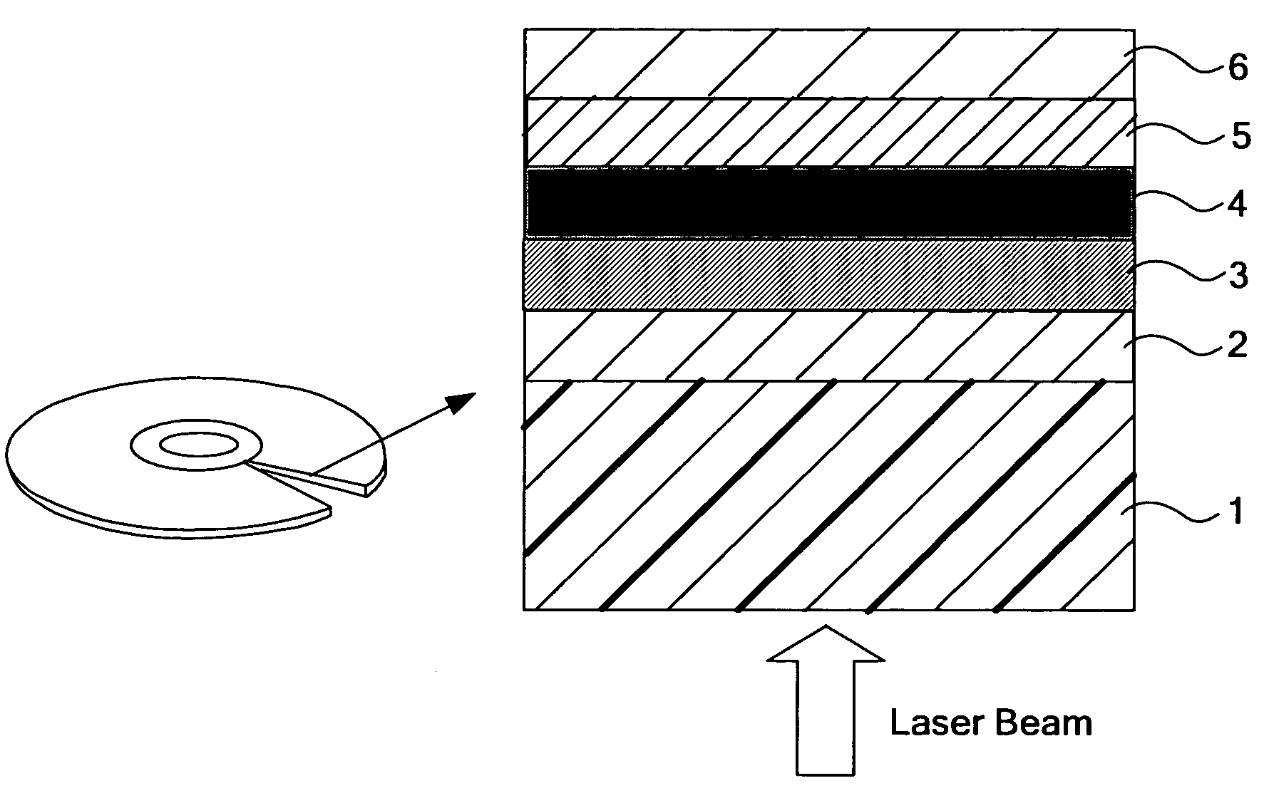
Preparation of Phase-Change Information Recording Medium
[0132]A phase-change information recording medium (disc) was prepared as follow. Sputtering was conducted using a sheet sputtering apparatus (Big Sprinter by Unaxis Incorporated) under Ar gas atmosphere with electricity input of 1 kW to 5 kW and Ar gas pressure of 2×10⁻³ Torr.
[0133]A polycarbonate resin substrate of 0.74 μm track pitch, 27 nm groove depth, 12 cm diameter and 0.6 mm thickness was provided.
[0134]First, using a sputtering target of (ZnS)80 (SiO2)20 composition (mole percent), a first protective layer of 80 nm thickness was formed on the substrate by sputtering.
[0135]Next, using a sputtering target of Sn5Sb75Ga13Ge7 composition (atomic percent), a phase-change recording layer of 20 nm thickness was formed on the first protective layer by sputtering.
[0136]Next, using the sputtering target of (ZnS)80 (SiO2)20 composition (mole percent), a second protective layer of 14 nm thickness was formed on the phase-change recor...
example 2
Preparation of Phase-Change Information Recording Medium
[0141]The phase-change information recording medium of Example 2 was prepared similarly to Example 1, except for forming a phase-change recording layer by sputtering using a sputtering target of Sn25Sb56Ga9Ge10 composition (atomic percent).
example 3
Preparation of Phase-Change Information Recording Medium
[0142]The phase-change information recording medium of Example 3 was prepared similarly to Example 1, except for forming a phase-change recording layer by sputtering using a sputtering target of Sn24Sb41Ga18Ge17 composition (atomic percent).
PUM
| Property | Measurement | Unit |
|---|---|---|
| thickness | aaaaa | aaaaa |
| linear velocity | aaaaa | aaaaa |
| speeds | aaaaa | aaaaa |
Abstract
Description
Claims
Application Information