Ion optics systems

a technology of optics and ion optics, applied in the field of ion optics systems, can solve the problems of limiting the resolution of a tof mass analyzer, performance of tof mass spectrometer instruments, and limiting the resolving power

Inactive Publication Date: 2008-10-21
MDS CO LTD
View PDF13 Cites 9 Cited by
  • Summary
  • Abstract
  • Description
  • Claims
  • Application Information

AI Technical Summary

Benefits of technology

[0001]Time-of-flight (TOF) mass spectrometry (MS) has become a widely used analytical technique. Two important metrics of mass spectrometry instrumentation performance are resolving power and sensitivity. In mass spectrometry, the mass resolving power of a measurement is related to the ability to separate ions of differing mass-to-charge ratio (m / z) values. The sensitivity of a mass spectrometry instrument is related to the efficiency of ion transmission from source to detector, and the efficiency of ion detection. In various mass spectrometers, including TOF instruments, it is possible to improve the resolving power at the expense of sensitivity, and vice versa.
[0002]There are several aspects of TOF MS that can inherently limit the resolution of a TOF mass analyzer. Specifically, ions can be formed in the source region at different times, at different positions, and with different initial velocities. These spreads in ion formation time, position and velocity can result in some ions with the same m / z achieving different kinetic energies (and some ions with different m / z achieving the same kinetic energy) due to differences in the length of time they spend in the extracting electrical field, differences in the strength of the electrical field where they are formed, and / or different initial kinetic energies. As a result, the resolving power and performance of the TOF mass spectrometer instrument can be degraded.
[0009]The present teachings provide ion optics systems comprising two or more pairs of ion condensers arranged where the first member and second member of each pair are disposed on opposite sides of a first plane such that the first member of the pair has a position that is substantially mirror-symmetric about the first plane relative to the position of the second member of the pair, and where the deflection angle, θ, for each ion condenser is less than or equal to about π radians. In various embodiments, the present teachings provide ion optics systems that can provide energy focusing of ions with substantially no spatial dispersion due to differences in kinetic energy the ions may have had on entering the ion optics system. It is to be understood that differences in ion kinetic energy due to other processes that might arise after ions enter the ion optics system (e.g., including, but not limited to, space charge effects, ion fragmentation, etc.) are not considered by the present teachings to be differences in kinetic energy the ions have on entering the ion optics system. In various embodiments, the ion optic systems provide an ion trajectory exiting the ion optics system that is substantially parallel to the corresponding ion trajectory entering the ion optics system. In various embodiments, the ion condensers can be arranged such that the ion trajectory exiting the ion optics system is substantially coincident with the corresponding ion trajectory entering the ion optics system. The ion optic systems of the present teachings can include, for example, one or more ion-focusing elements (e.g., an einzel lens), and ion-steering elements (e.g., deflector plates), for example, to provide a substantially parallel input ion beam.
[0013]In various embodiments of an ion optics system of the present teachings, the ion optics system comprises an ion selector. For example, in various embodiments, an ion optics system comprises two or more pairs of ion condensers where the members of each pair of ion condensers are disposed on opposite sides of a first plane such that the first member of a pair of ion condensers has a position that is substantially mirror-symmetric about the first plane relative to the position of the second member of the pair, each of the ion condensers having a deflection angle, θ, less than or equal to about π radians, and at least one ion selector positioned between two of the ion condensers, for example, to prevent the transmission of ions with select kinetic energies. Such placement can take advantage of the energy dispersion that can exist between ion condensers of the ion optics system. Suitable ion selectors include any structure that can prevent the transmission of ions based on ion position.

Problems solved by technology

There are several aspects of TOF MS that can inherently limit the resolution of a TOF mass analyzer.
As a result, the resolving power and performance of the TOF mass spectrometer instrument can be degraded.
In many cases a major factor limiting resolving power can be the spread in kinetic energy of the ions.
In many applications this may not be a problem, but in others it can limit both the resolving power and the sensitivity of the mass analyzer.
However, applications where the ion mirror is used in the first stage of a TOF-TOF system, energy dispersion in the first stage can cause significant losses in both sensitivity and resolving power in the second stage of the instrument.

Method used


Image

  • Ion optics systems
  • Ion optics systems
  • Ion optics systems

Examples


Embodiment Construction

[0030]To better understand the present teachings, examples of the behavior of ions in a single ion condenser and in two ion condensers in series are provided.

Single Ion Condenser

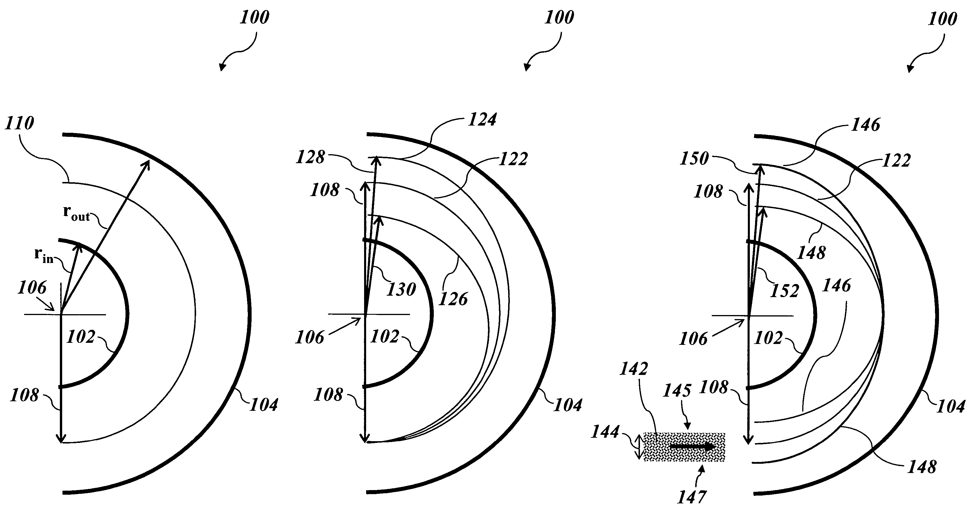
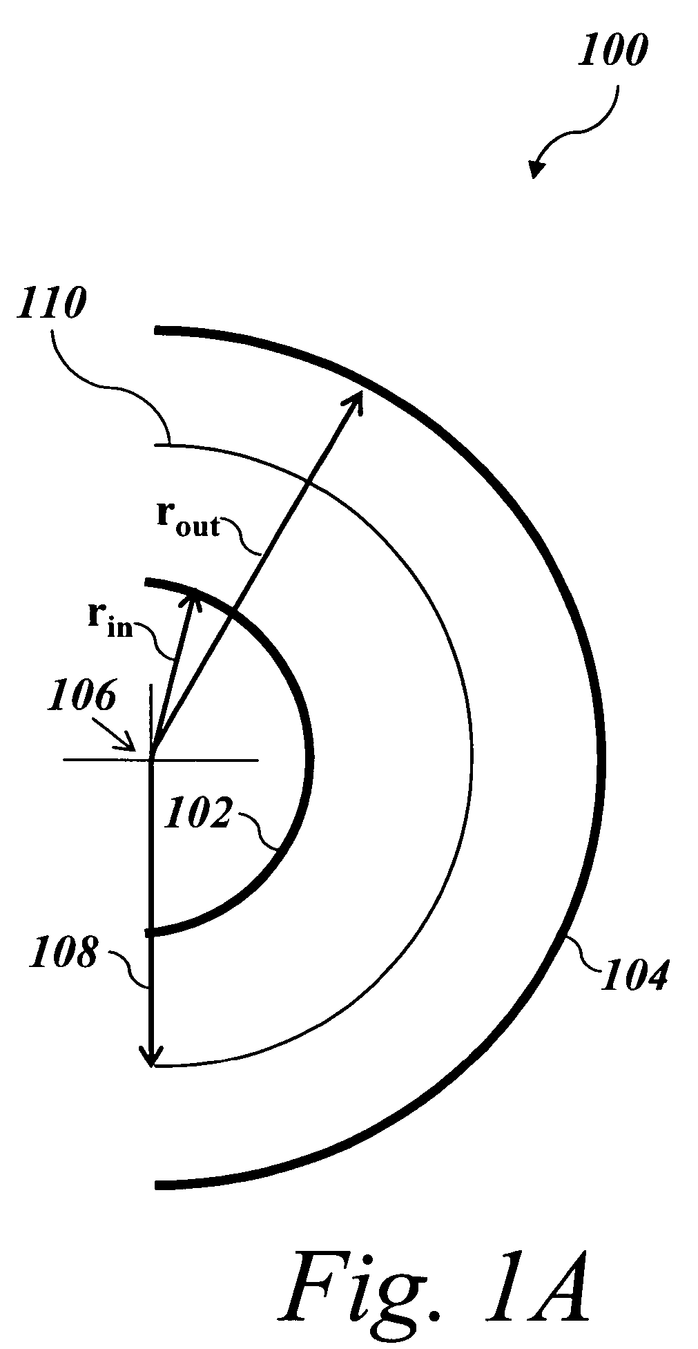
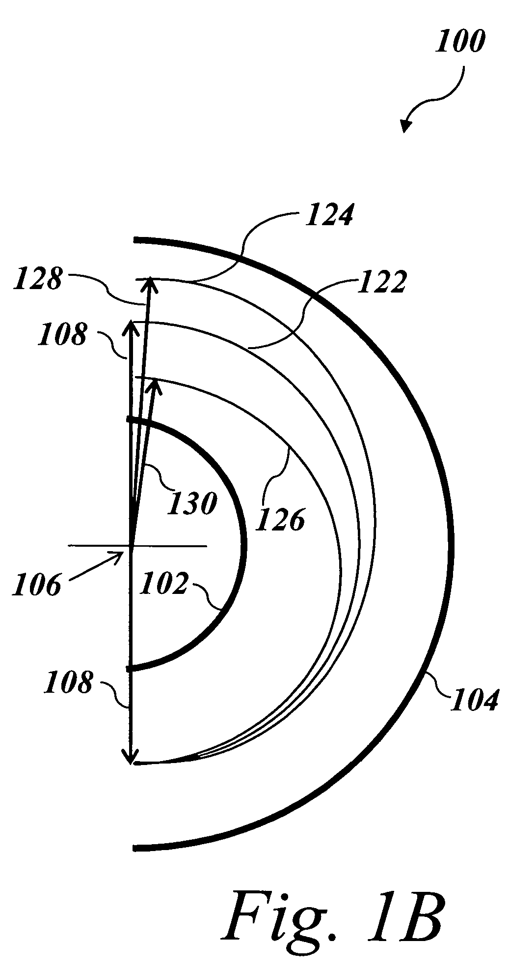
[0031]To better understand the present teachings, an example of the behavior of ions in a single 180 degree spherical ion condenser employing a static electrical field is schematically illustrated in FIGS. 1A-1C. In a single spherical ion condenser 100, employing a static electrical field, ions enter the electrical field formed by a pair of hemispheric electrodes 102, 104. In this illustration, the ions are produced from an ion source at potential V0 and, for convenience of notation and conciseness, the electrodes are considered to be biased so that ground or zero potential is at the nominal radius r0. The angular momentum, l, and the total energy, E, are constants of the motion of an ion in an ion condenser and for a given set of initial conditions define the ion trajectory.

[0032]The angular momentum, l, of...


PUM


Abstract

In various embodiments, provided are ion optics systems comprising two or more pairs of ion condensers arranged where the first member and second member of each pair are disposed on opposite sides of a first plane such that the first member of the pair has a position that is substantially mirror-symmetric about the first plane relative to the position of the second member of the pair and wherein the deflection angle of each of the ion condensers is less than or equal to about π radians.

Description

INTRODUCTION[0001]Time-of-flight (TOF) mass spectrometry (MS) has become a widely used analytical technique. Two important metrics of mass spectrometry instrumentation performance are resolving power and sensitivity. In mass spectrometry, the mass resolving power of a measurement is related to the ability to separate ions of differing mass-to-charge ratio (m / z) values. The sensitivity of a mass spectrometry instrument is related to the efficiency of ion transmission from source to detector, and the efficiency of ion detection. In various mass spectrometers, including TOF instruments, it is possible to improve the resolving power at the expense of sensitivity, and vice versa.[0002]There are several aspects of TOF MS that can inherently limit the resolution of a TOF mass analyzer. Specifically, ions can be formed in the source region at different times, at different positions, and with different initial velocities. These spreads in ion formation time, position and velocity can result ...

Claims


Application Information

Patent Timeline
Patent Type & Authority Patents(United States)
IPC IPC(8): H01J49/00H01J49/48
CPCH01J49/06H01J49/48H01J2237/053
Inventor VESTAL, MARVIN L.
Owner MDS CO LTD
Why Eureka
Try Eureka