
Laser plasma spectroscopy apparatus and method for in situ depth profiling

a plasma spectroscopy and depth profiling technology, applied in the field of depth profiling, can solve the problems of reducing airflow and thus efficiency, damaging metal parts of machinery, buckets, blades,

Active Publication Date: 2008-10-21
GENERAL ELECTRIC CO
View PDF18 Cites 17 Cited by
  • Summary
  • Abstract
  • Description
  • Claims
  • Application Information

AI Technical Summary

Benefits of technology

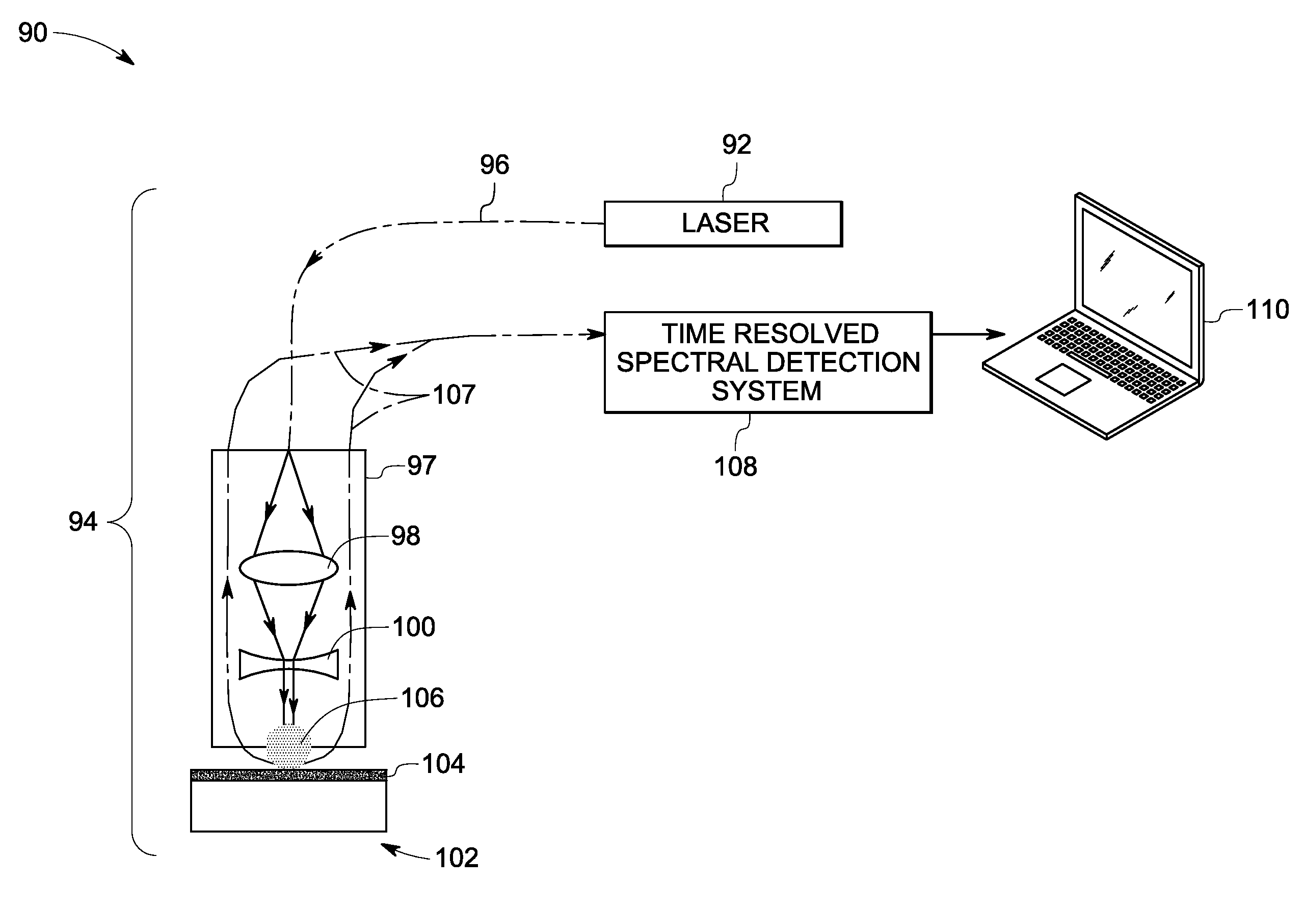
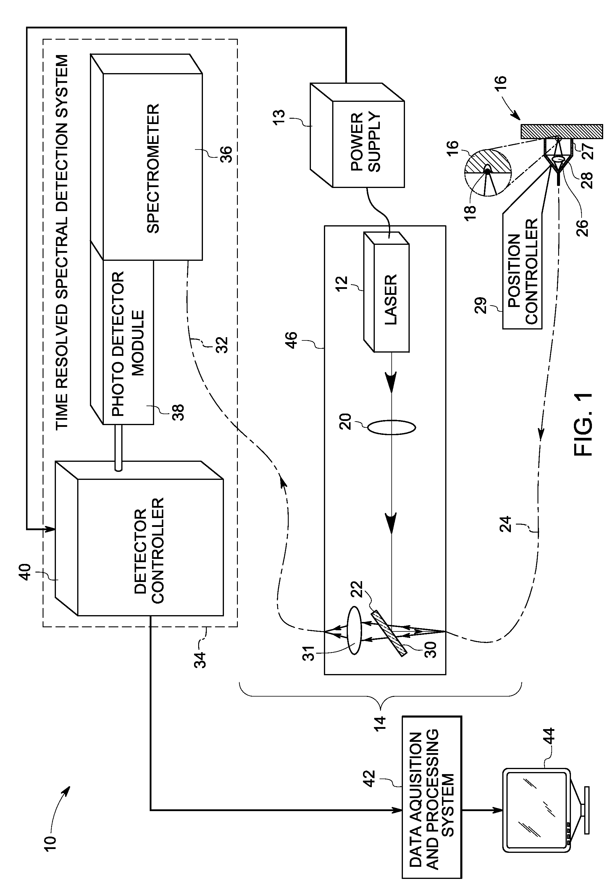
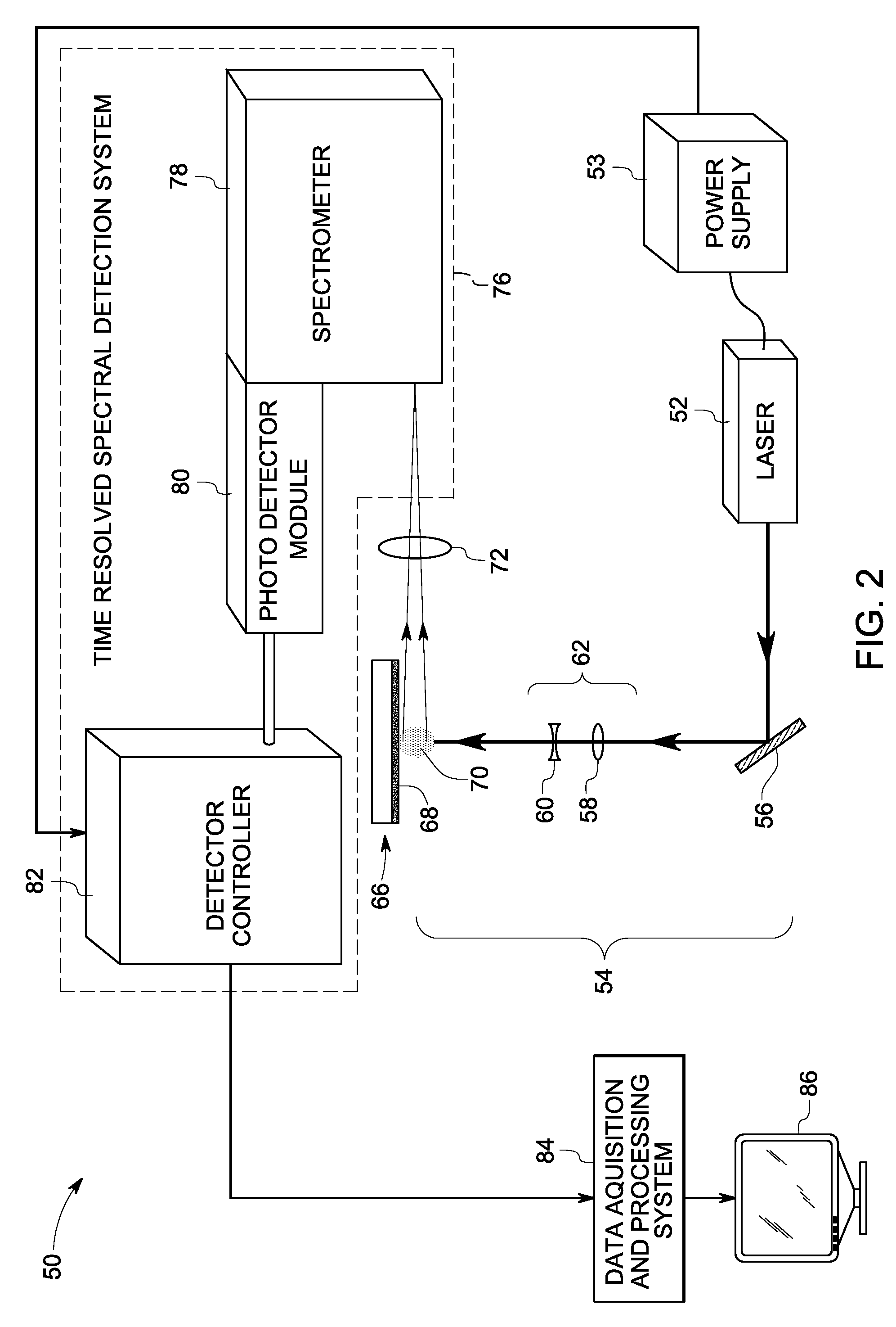
The present invention is a system and method for in-situ laser plasma spectroscopy (LPS) that allows for automated near real-time elemental depth profiling of a target or coating. The system includes an optical source, an optical probe system, a time resolved spectral detection system, and a data acquisition and processing system. The optical probe system delivers a pulsed optical beam to the surface of the target or coating to generate an ablation plasma, which is then detected using the time resolved spectral data. The data is processed to determine the absolute elemental concentration of the target or coating as a function of depth in near real-time. The technical effects of this invention include improved accuracy and efficiency in elemental depth profiling, as well as reduced damage to the target or coating during the analysis process.

Problems solved by technology

Exposure to high temperatures for extended periods of time can damage metal parts of machinery such as buckets, blades, and nozzles in turbine engines.
In gas turbine engines, such damage can result in a reduction in airflow and thus efficiency.
Damage to blades can eventually lead to failure of the engine.
Although the coatings extend the lifetime of the metal components, the coatings themselves are affected by this exposure over time.
Although a number of analytical techniques exist for measuring elemental concentration as a function of depth, they all either invoke destructive analysis of the part or substrate (e.g., secondary ion mass spectroscopy and electron microprobe analysis) or cannot be performed remotely or in situ (e.g., laser ablation mass spectroscopy), especially in real time.

Method used


Image

  • Laser plasma spectroscopy apparatus and method for in situ depth profiling
  • Laser plasma spectroscopy apparatus and method for in situ depth profiling
  • Laser plasma spectroscopy apparatus and method for in situ depth profiling

Examples


examples

[0049]A “free space” optical probe system configuration of the laser plasma spectroscopy system as shown in FIG. 2 was built in accordance with one embodiment of the present invention. The system included a Nd:YAG laser configured to emit ˜45 mJ laser pulses at a wavelength of 1064 nm at 20 Hz repetition rate. A collimating element including positive and negative lenses was used to generate a collimated beam of about 600 microns in diameter with a flat topped uniform intensity profile. As used herein the term “flat topped uniform intensity profile” refers to an intensity profile capable of producing an optical illumination zone of substantially uniform optical energy for target ablation with one example being shown in FIGS. 6 and 7. FIG. 6 shows the 3 dimensional (3D) profile of the ˜45 mJ laser beam pulses at a target surface distance. The 3D plot of the intensity 118 versus the beam spot dimensions along the Y-axis 120 and X-axis 122 shows a substantially flat-topped, uniform inte...


PUM

PropertyMeasurementUnit
timeaaaaaaaaaa
timeaaaaaaaaaa
wavelengthaaaaaaaaaa

Abstract

An in-situ laser plasma spectroscopy (LPS) system for automated near real-time elemental depth profiling of a target including: an optical source configured to generate an optical beam, wherein the optical beam is pulsed; an optical probe system configured to deliver the optical beam from the optical source to a surface of a target to generate an ablation plasma; a time resolved spectral detection system configured to generate time resolved spectral data from emission signals from the ablation plasma; and a data acquisition and processing system configured to acquire the time resolved spectral data to determine, in combination with predetermined calibration data, an absolute elemental concentration as a function of depth in near real-time.

Description

BACKGROUND[0001]The invention relates generally to depth profiling and more particularly to depth profiling using laser plasma spectroscopy.[0002]Exposure to high temperatures for extended periods of time can damage metal parts of machinery such as buckets, blades, and nozzles in turbine engines. In gas turbine engines, such damage can result in a reduction in airflow and thus efficiency. Damage to blades can eventually lead to failure of the engine. Coatings are frequently used to protect metal parts such as turbine blades from the effects of high temperature exposure for extended time periods that can damage the blades and reduce lifetime. Although the coatings extend the lifetime of the metal components, the coatings themselves are affected by this exposure over time.[0003]Currently, all the buckets, blades, and nozzles are stripped and recoated after a given exposure interval, or the engine is partially disassembled and a sample part is removed and sacrificed for analysis. Both ...

Claims


Application Information

Patent Timeline
Patent Type & Authority Patents(United States)
IPC IPC(8): G01J3/443G01B11/22G01J3/30G01N21/63G01B11/06
CPCG01J3/2889G01J3/443G01N21/718G01N2021/1782
Inventor BENICEWICZ, PAMELA KINGFOMITCHOV, PAVEL ALEXEYEVICHROZIER, ELENAVIERTL, JOHN RUEDIGER MADERSCHUMAKER, TYMM BRADNER
Owner GENERAL ELECTRIC CO
Learn More