Will call wireless tank level monitoring system

a wireless and monitoring system technology, applied in liquid handling, instruments, packaged goods types, etc., can solve the problems of rural customers being left without fuel for heating, cooking, and inability to guarantee that the user does not run out of fuel,

Active Publication Date: 2008-10-28
INVENSYS SYST INC
View PDF16 Cites 46 Cited by
  • Summary
  • Abstract
  • Description
  • Claims
  • Application Information

AI Technical Summary

Benefits of technology

[0009]In view of the above, it is an objective of the present invention to provide a new and improved tank level monitoring system that overcomes the above described and other problems existing in the art. More specifically, it is an objective of the present invention to provide a new improved wireless tank level monitoring system that may be used with residential fuel tank installations to provide remote indication of fuel tank level. As such, the wireless fuel tank level monitoring system alleviates the requirement that a user physically go to the storage tank to read the level gauge installed thereon.
[0010]In view of these objectives, an embodiment of the wireless tank level monitoring system includes a transmitter module and a base station. Preferably, the transmitter module is located at or on the fuel storage tank, and the base station is located within the user's dwelling or other convenient location easily accessible by the user. In a highly preferred embodiment, mounting of the transmitter module is accommodated by a plastic holster that may be installed on the storage tank, dome, lifting eye or gas line. The transmitter module uses a transducer that is coupled to a level sensing apparatus, such as a remote-ready tank level gauge, a Hall effect switch, a magneto-resistive sensor, etc. In one embodiment, the transmitter module continuously reads the output from the sensing apparatus, e.g. the remote-ready level gauge, Hall effect switch, etc., and transmits this information to the base station for display to the user. In preferred embodiments, however, to extend the operating life in battery operated embodiments, the transmitter sleeps, periodically waking to measure the level and transmit the reading to the base station.

Problems solved by technology

Despite the premium paid by the user, such a scheduled delivery service also cannot guarantee that the user does not run out of fuel between scheduled deliveries.
That is, if a particularly cold snap occurs between the scheduled deliveries or if the user simply uses more fuel during that period than has been typical, there is a possibility that the tank may run empty before the fuel truck returns to refuel the storage tank.
As a result, the rural customer may be left without fuel for heating, cooking, etc.
The problem with such a will call system is that it requires the user to physically go to the storage tank and read a gauge installed thereon.
Since the storage tanks are not typically installed in close physical proximity to the residence, and since the largest usage of such fuel occurs during the winter and in extremely cold temperatures, the users are forced to be exposed to such cold temperatures, snow, etc. while they walk to the storage tank, read the gauge, and return to the residence.
Because this chore is not pleasant during periods of extreme cold, users often put off checking their tanks.
Unfortunately, the rate at which the user consumes this fuel is typically greater than normal during such periods.
As a result, many users inadvertently run out of fuel before they can schedule a refill simply because they did not want to experience the unpleasantness of having to hike to their fuel storage tank during such bad weather.
As a result, they may be forced to pay an extra emergency delivery charge or endure periods without heat until the delivery truck can return to refuel their storage tank.

Method used


Image

  • Will call wireless tank level monitoring system
  • Will call wireless tank level monitoring system
  • Will call wireless tank level monitoring system

Examples


Embodiment Construction

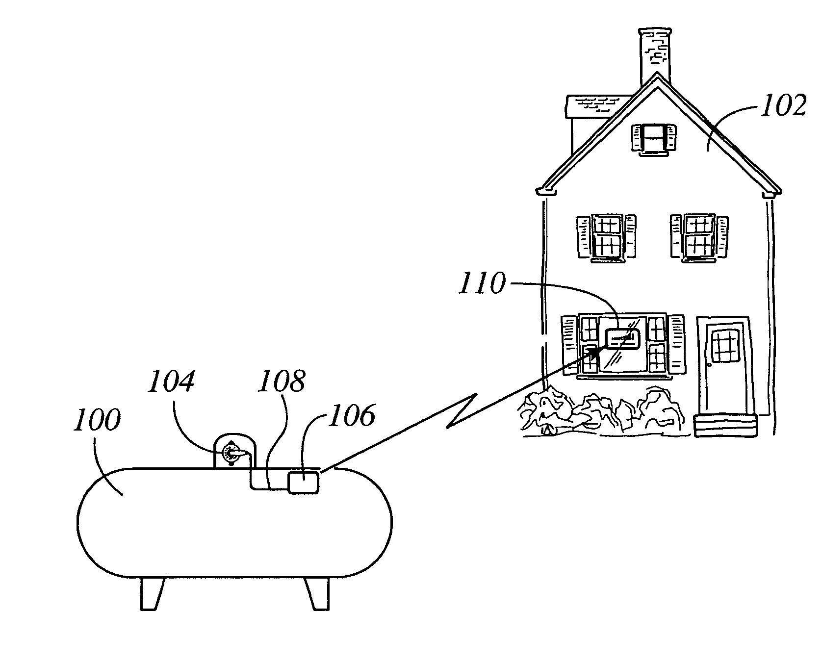
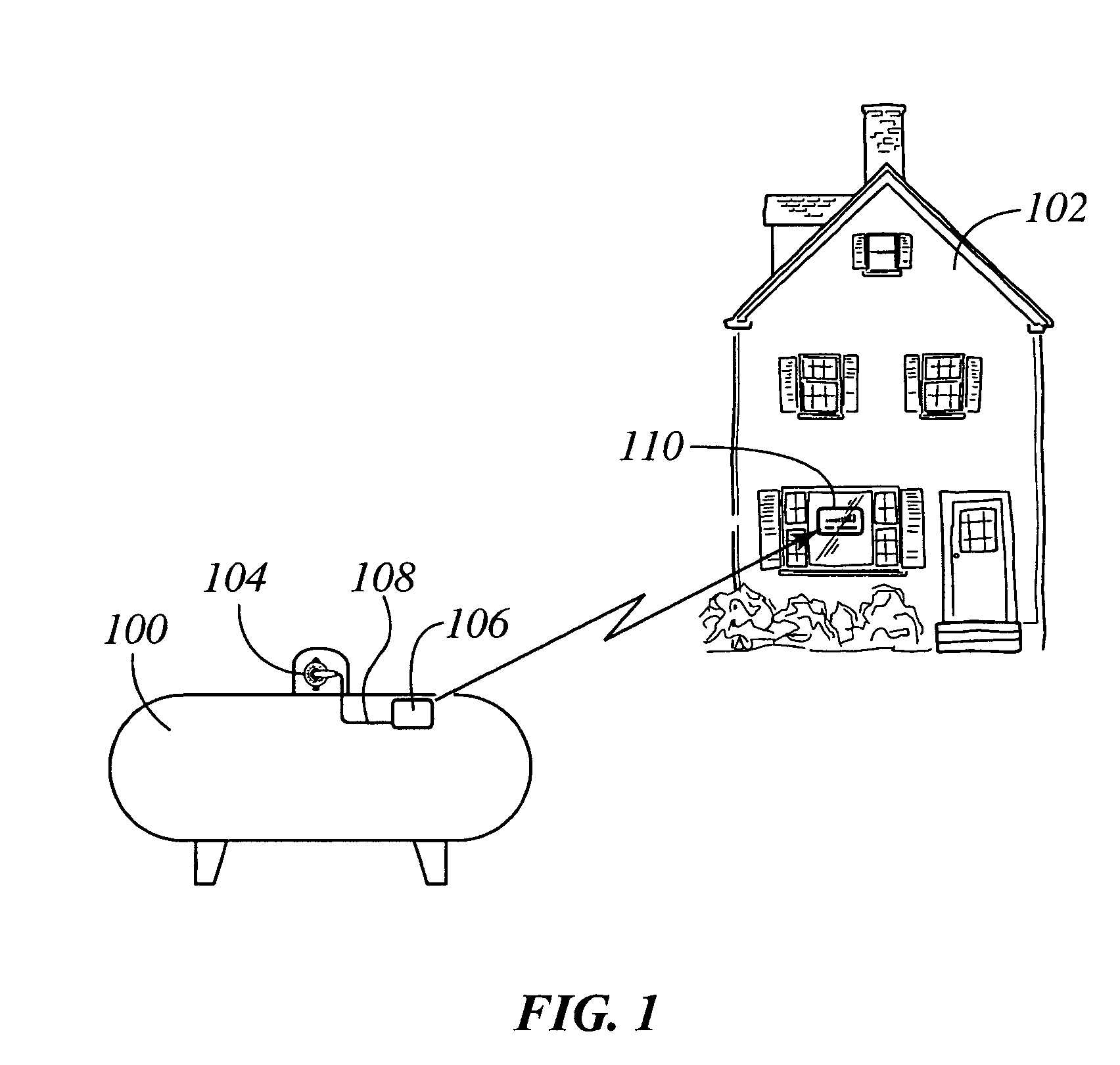
[0023]In the description that follows, the system of the present invention will be described in an operating environment in which a rural residential customer utilizes liquid propane (LP) gas for heating, cooking, etc. In this operating environment, the rural customer utilizes an above-ground LP gas storage tank 100 to store the propane that it utilizes to heat his residence 102, with which to cook food, etc. As is typical, the LP storage tank 100 is located on the user's property at a location remote from the dwelling 102 for safety reasons. It should be recognized, however, that the particular type of fuel used by the residential customer is not limiting on the scope of the present invention. Indeed, the tank level sensing system of the present invention may be applied to water level sensing in, e.g., a cistern. As such, this operating environment is provided by way of illustration only, and not by way of limitation. Of course, different types of fuels and other liquids may requir...


PUM

PropertyMeasurementUnit
line-of-sight distanceaaaaaaaaaa
ratiometric voltageaaaaaaaaaa

Abstract

A wireless tank level monitoring system is provided. The system includes a transmitter that is located in close proximity to the storage tank. The transmitter is coupled to a remote-ready tank level gauge, which provides a ratio-metric voltage output proportional to the liquid volume inside the tank. The transmitter periodically monitors the output from the level gauge and transmits the information to a base station located remotely from the storage tank. The base station displays the tank level numerically in percent full, graphically with a bar chart, or both. A conspicuous visual indication is provided by the base station when the tank level drops below a predetermined set point. In battery powered applications, the base station also reads and provides a visual indication of a low battery condition for both the transmitter and base station.

Description

FIELD OF THE INVENTION[0001]The present invention relates to tank level monitoring systems, and more particularly to wireless tank level monitoring systems for use with residential fuel tanks such as propane, water tanks, cisterns, etc.BACKGROUND OF THE INVENTION[0002]While most homes in an urban environment receive natural gas through a centralized distributed system throughout the city for use in heating their homes, most rural homes and farms rely on liquid fuel storage tanks installed on their property to supply the needed fuel for heating, cooking, etc. In such rural environments where a distributed pipeline system does not exist, fuel tank trucks actually deliver the fuel to the individual farms and residences, fill their onsite storage tanks, and leave. The users then draw from the tank as needed to supply their home and outbuildings with heat and for cooking, and occasionally for the generation of electricity. Often, the fuel of choice for these rural installations is liquid...

Claims


Application Information

Patent Timeline
Patent Type & Authority Patents(United States)
IPC IPC(8): B65B1/30E03B7/07G01F19/00
CPCG01F23/0069G01F23/18Y10T137/8342G01F23/802
Inventor LEASE, BENJAMIN N.
Owner INVENSYS SYST INC
Why Eureka
Try Eureka