Optical waveguide vibration sensor for use in hearing aid

a vibration sensor and waveguide technology, applied in the field of optical waveguide vibration sensor for use in hearing aids, can solve the problems of large power consumption of devices, large battery packs and body-worn accessories, and ineffective hearing aids for people with severe or profound sensori-neural hearing loss

Inactive Publication Date: 2008-11-04
RGT UNIV OF CALIFORNIA
View PDF15 Cites 91 Cited by
  • Summary
  • Abstract
  • Description
  • Claims
  • Application Information

AI Technical Summary

Problems solved by technology

Similarly, vibration dectectors may provided on industrial equipment such as engines, valves, pumps, fans and the like to indicate dangerous conditions.
However, hearing aids are generally ineffective for people with severe or profound sensori-neural hearing loss.
However this technology requires relatively large and expensive microelectronic chipsets that consume large amounts of power, typically 150-750 mW for a cochlear implant.
Consequently, the devices require large battery packs and body-worn accessories to produce the electrical signals needed for the deaf to hear.
Furthermore, the battery life is often limited to less than a day, requiring frequent recharging of the devices.
The expense, bulky size, and weight of the current technology means that the majority of the hearing impaired population cannot truly benefit from the technology.
Small DSP-based devices are prohibitively expensive to most people.
Body-worn accessories and frequent re-charging requirements make the devices less desirable for active people and children, resulting in a significant impact on the quality of life for the hearing impaired members of the population.
Another disadvantage of some currently available hearing devices is that they are not directionally sensitive.
As a result, the user can hear sounds, but can not tell where the sounds are coming from.
This can be a safety issue in certain situations, for instance for drivers or pedestrians who need to know where they are in relation to oncoming vehicles before they can see them.
First, the natural range of frequencies for this device could not extend to the low frequencies (under 1 kHz).
Third, there was no easy way to convert the vibrating silicon cantilevers into electrical energy.

Method used


Image

  • Optical waveguide vibration sensor for use in hearing aid
  • Optical waveguide vibration sensor for use in hearing aid
  • Optical waveguide vibration sensor for use in hearing aid

Examples


Embodiment Construction

[0039]The following detailed description and the accompanying drawings are provided for purposes of describing and illustrating the presently preferred embodiments of the invention only, and are not intended to limit the scope of the invention in any way.

DETAILED DESCRIPTION AND EXAMPLES

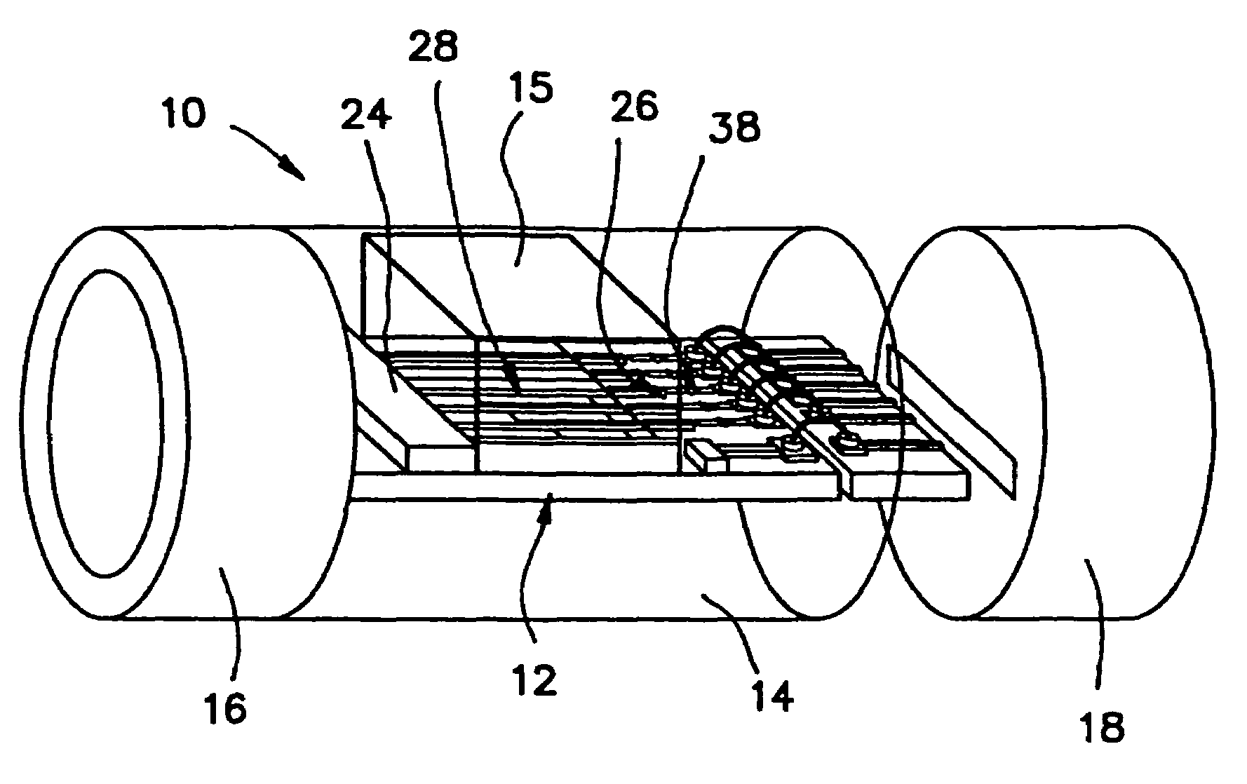
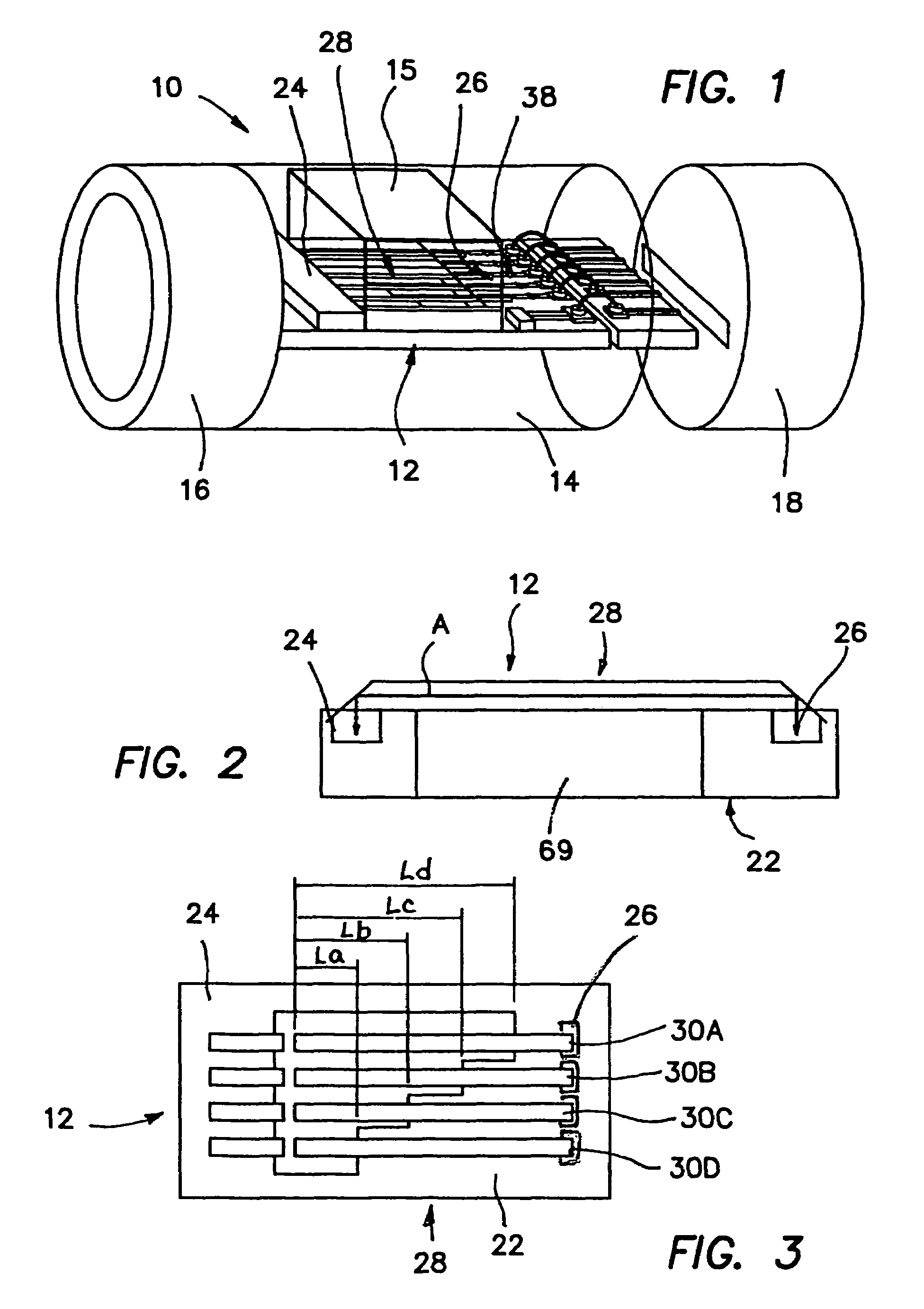
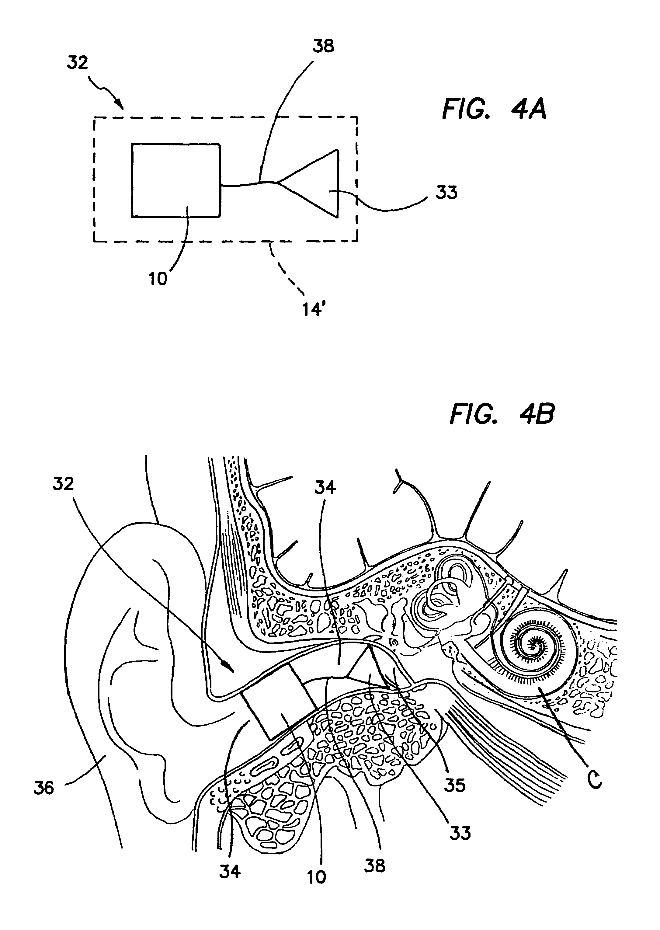
[0040]FIG. 1 illustrates a hearing enhancement device 10 incorporating a vibration detector / transducer 12 according to the present invention. The vibration detector / transducer 12 is a micro-electrical-mechanical system (MEMS) encased in a device housing 14 (shown here in phantom), which includes an opening 15 for allowing sound to reach the MEMS. The device housing 14 is coupled at one end to a battery housing 16 containing a battery for powering the vibration detector / transducer 12 and at the opposite end to an adapter or end cap 18 configured to facilitate physical interface between the vibration detector / transducer 12 and the inner ear of a hearing-impaired patient.

[0041]Turning now to FIGS. 2 and...


PUM

PropertyMeasurementUnit
Young's Modulusaaaaaaaaaa
poweraaaaaaaaaa
frequency selectivityaaaaaaaaaa

Abstract

A directionally-sensitive device for detecting and processing vibration waves includes an array of polymeric optical waveguide resonators positioned between a light source, such as an LED array, and a light detector, such as a photodiode array. The resonators which are preferably oriented substantially perpendicularly with respect to incoming vibration waves, vibrate when a wave is detected, thus modulating light signals that are transmitted between the light source and the light detector. The light detector converts the modulated light into electrical signals which, in a preferred embodiment, are used to drive either the speaker of a hearing aid or the electrode array of a cochlear implant. The device is manufactured using a combination of traditional semiconductor processes and polymer microfabrication techniques.

Description

RELATED APPLICATIONS[0001]This application claims the benefit of U.S. Provisional Application Ser. No. 60 / 404,834 filed Aug. 20, 2002. The entire disclosure of this provisional application is expressly incorporated herein by reference.FIELD OF THE INVENTION[0002]The present invention relates generally to devices and methods for detecting vibrations and converting such vibrations into electrical signals In a particularly useful embodiment, the invention relates to a method and device for enhancing hearing in a human or veterinary patient, and to methods of making and using the device.BACKGROUND OF THE INVENTION[0003]Vibration detectors and transducers are used in a wide variety of applications. For instance, vibration detectors may be incorporated into buildings, bridges, or other structures to warn of seismic or other potentially destructive vibrations. Similarly, vibration dectectors may provided on industrial equipment such as engines, valves, pumps, fans and the like to indicate ...

Claims


Application Information

Patent Timeline
Patent Type & Authority Patents(United States)
IPC IPC(8): G01D5/353H04R25/02G01D21/00G01H9/00
CPCG01H9/006H04R23/008H04R19/016Y10T29/49005Y10T29/49572H04R25/00G01H9/00
Inventor LI, GUANN-PYNGBACHMAN, MARKXU, TAOZENG, FAN-GANGCOFFEY, PATRICK
Owner RGT UNIV OF CALIFORNIA
Why Eureka
Try Eureka