
Photosensitive composition for manufacturing optical waveguide, production method thereof and polymer optical waveguide pattern formation method using the same

a technology of optical waveguides and compositions, applied in the field of polymer optical waveguide pattern formation, can solve the problems of difficult simultaneous realization of difficult to realize intermixing between core and clad layer, and difficult to achieve heat stability and optical isotropy, etc., to achieve simple pattern formability, reduce the effect of overlapping

Inactive Publication Date: 2004-09-09
NIPPON TELEGRAPH & TELEPHONE CORP
View PDF2 Cites 9 Cited by
  • Summary
  • Abstract
  • Description
  • Claims
  • Application Information

AI Technical Summary

Benefits of technology

[0029] Here, the photosensitive composition for optical waveguides is cationic photopolymerizable, and the crosslinking agent capable of greatly activating the photopolymerizability of said silicone oligomer as a main component of the composition may have at least an epoxy moiety or an alkoxysilane moiety in the molecule.
[0036] In a seventh aspect of the present invention, a method of producing the above photosensitive composition for optical waveguides comprising the steps of: heating a silicone oligomer and a crosslinking agent in the presence of a solid catalyst; and filtering the solid catalyst, concentrating filtrate, and further adding a polymerization initiator. With this method, initiation of optical crosslinking is remarkably improved.
[0038] The inventors have found that these reactive oligomers have a simple pattern formability and are capable of forming a polymer optical waveguide pattern which has superior heat stability and moisture resistance, small birefringence and is easy to connect to optical components, and accomplished the present invention.
[0039] Specifically, the present invention is capable of forming a waveguide ridge pattern having a sharp and smooth wall surface by curing a film by irradiation with light and developing by an appropriate solvent. Further, although it has been very difficult to perform waveguide processing in a thick film polymer with material in prior art, the present invention can easily process the waveguide even with a thick film. Still further, with the present invention, birefringence of the photocured of liquid oligomer is reduced to less then 1.times.10.sup.-3, and polarization dependence can be reduced to less than the tolerance limit. Yet further, by controlling the molecular weight of the polymer optical material, an appropriate viscosity suitable for the thin film formation process can be obtained.

Problems solved by technology

However, heat stability and optical isotropy are difficult to realize simultaneously because the rigid or resilient skeleton to improve the heat stability as described above promotes orientation of molecule.
When a high molecular-weight polymer material is spin-coated from a solution, an intermixing between core and clad layer tends to occur, which is often a problem in waveguide processability.
Polymer optical materials have been considered to have problems in terms of environmental resistance such as heat stability or moisture resistance.
Consequently, there is very few material which meets all of such requirements at the same time.
As described above, silicone resin has superior characteristics as an optical waveguide material, but processability has not been satisfactory.
For example, dry etching in the production of a core ridge requires a long time and a plurality of processes, like an inorganic material such as glass or semiconductor.
However, in these methods, bond between side chains by crosslinking is dominant rather than siloxane bond, which generates problems not only in heat stability but also in an inevitable increase in optical propagation loss due to increase in ratio of hydroxy group in the case of epoxy or due to increase in ratio of hydrocarbon in the case of vinyl ether or acrylics.
In particular, this is a problem when the waveguide is actually used as a single mode optical waveguide.
However, this method has a disadvantage because it makes the construction of the optical device substantially complicated.
However, according to intensive studies conducted by the inventors, it is very rare that sufficient crosslinking is actually achieved by a combination of only a silicone oligomer and a cationic photopolymerization initiator.
In addition, the higher the molecular weight of the oligomer, the more crosslinking tends to proceed, however repeatability is poor and the effect is insufficient.
Furthermore, this method can not be a general-purpose technique since an increase in molecular weight of the material itself is difficult when composition of substituent is rich in aromatic groups.
Sufficient crosslinking is rarely achieved depending on the type of silicone oligomer and heating condition, however, in most cases, crosslinking is insufficient and there are problems in repeatability as in the above-described cases.
Thus, the bond between side chains by crosslinking is dominant rather than the strong siloxane bond, which generates not only problems such as heat stability but also an inevitable increase in optical propagation loss due to increase in proportion of hydroxy group in the case of epoxy and increase in proportion of hydrocarbon in the case of vinyl ether or acrylic.

Method used


Image

  • Photosensitive composition for manufacturing optical waveguide, production method thereof and polymer optical waveguide pattern formation method using the same
  • Photosensitive composition for manufacturing optical waveguide, production method thereof and polymer optical waveguide pattern formation method using the same
  • Photosensitive composition for manufacturing optical waveguide, production method thereof and polymer optical waveguide pattern formation method using the same

Examples


example 1

[0069] Phenyltrichlorosilane (211.5 g) and methyltrichlorosilane (36.3 g) were dissolved in 1 liter of anhydrous tetrahydrofuran, and 3 equivalents of water (67.5 g) was slowly added dropwise to the solution so that the liquid temperature does not increase. After that, 315 g of sodium hydrogencarbonate was added while agitating the reaction liquid. After the completion of carbon dioxide gas evolution, agitation was continued for further 1 hour. Next, the reaction liquid was filtered, then tetrahydrofuran was distilled out by a rotary evaporator to give a colorless, transparent viscous liquid. Further, this liquid was vacuum dried to give an oligomer A. The molecular weight of resulting oligomer A was measured by GPC and the result was Mw=3300, Mn=1500.

[0070] Next, a photosensitive substance A was prepared which comprises 50 g of oligomer A, 25 g of UV resin, 2 weight % of N-benzyl-4-benzoylpyridi-nium hexafluoroantimonate as a photopolymerization initiator and 25 g of methylisobutyl...

example 2

[0072] A photosensitive substance B was prepared which comprises 50 g of the oligomer A produced in Example 1, 1 g of (3-glycidoxypropyl) trimethoxysilane as a crosslinking agent, 2 weight % of N-benzyl-4-benzoylpyridinium hexafluoroantimonate as a photopolymerization initiator, and 25 g of methylisobutylketone as a solvent.

[0073] Using the same procedure as in Example 1 except that the photosensitive substance B was used in place of the photosensitive substance A as a core part forming photosensitive substance, a buried type channel optical waveguide comprising a core-clad layer structure as shown in FIG. 1D was produced. In this case, the thickness of the upper clad is 8 .mu.m from the upper surface of the core. Further, no intermixing was noted between the lower clad layer and the core part formation layer.

[0074] As in Example 1, the resulting optical waveguide was cut to a length of 5 cm by a dicing saw, and measured for optical propagation loss which showed 0.5 dB / cm at wavelen...

example 3

[0075] Oligomer B was produced using the same procedure as in Example 1 except that deuterated phenyltrichlorosilane was used in place of phenyltrichlorosilane in the production of oligomer A in Example 1. and a photosensitive substance C was produced using the same procedure as in Example 2 except that oligomer B was used in place of oligomer A. Next, a buried type channel optical waveguide of core diameter 8 .mu.m.times.8 .mu.m was produced by the same process as in Example 2.

[0076] The resulting optical waveguide was cut to a length of 5 cm by a dicing saw, and measured for optical propagation loss which showed 0.1 dB / cm at wavelength 1.3 .mu.m, and 0.5 dB / cm or less at wavelength 1.55 .mu.m. Further, this optical propagation loss of the waveguide was unchanged for more than 1 month under the condition of 75.degree. C. / 90% RH.


PUM

PropertyMeasurementUnit
thicknessaaaaaaaaaa
thicknessaaaaaaaaaa
widthaaaaaaaaaa

Abstract

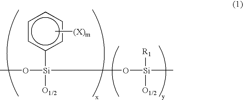
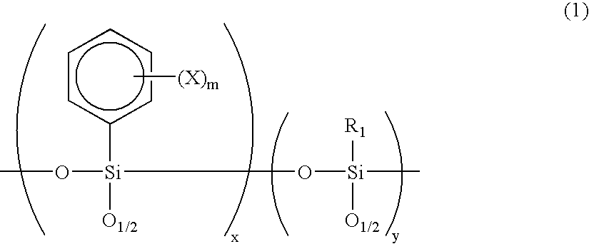
A photosensitive composition for optical waveguides comprising of an organic oligomer, a polymerization initiator and a crosslinking agent, the organic oligomer being a silicone oligomer represented by the following formula (1), wherein X denotes hydrogen, deuterium, halogen, an alkyl group or an alkoxy group; m is an integer from 1 to 5; x and y represent the proportion of respective units, and neither x nor y is 0; and R1 denotes a methyl, ethyl, or isopropyl group; a production method thereof, and a polymer optical waveguide pattern formation method using the same.

Description

[0001] This application is based on Patent Application No. 10-283142 filed on Oct. 5, 1998 in Japan, the content of which is incorporated hereinto by reference.[0002] 1. FIELD OF THE INVENTION[0003] The present invention relates to a polymer optical waveguide pattern formation method using a polymer material. The present invention can be utilized in various optical waveguides, optical integrated circuits, optical wiring boards and the like which are used in general optical and micro-optical areas and in optical communication or optical information processing areas.[0004] 2. DESCRIPTION OF THE RELATED ART[0005] Pushed by market requirements and national policy, construction of high-capacity optical fiber networks and preparation of FTTX (fiber to the X point) are being promoted. That is, WDM-MUX / DEMUX (Wavelength Division Multiplexing-Multiplexer / Demultiplexer) using an arrayed waveguide grating (AWG) as a key device has reached a practically applicable level, and a high-capacity an...

Claims


Application Information

Patent Timeline
Patent Type & Authority Applications(United States)
IPC IPC(8): G03F7/038G03F7/075
CPCG03F7/038G03F7/0757Y10S430/115Y10S430/106Y10S430/117
Inventor TOYODA, SEIJIIMAMURA, SABUROTOMARU, SATORUKURIHARA, TAKASHIENBUTSU, KOJIHAYASHIDA, SHOICHIMARUNO, TOHRU
Owner NIPPON TELEGRAPH & TELEPHONE CORP
Learn More