
Method of forming a biopsy device

a biopsy needle and biopsy tube technology, applied in the field of biopsy devices, can solve the problem that no single procedure is ideal for all cases, and achieve the effects of maintaining strength and stiffness characteristics, avoiding bruising, and avoiding bruising

Inactive Publication Date: 2008-11-04
DEVICOR MEDICAL PROD
View PDF15 Cites 41 Cited by
  • Summary
  • Abstract
  • Description
  • Claims
  • Application Information

AI Technical Summary

Benefits of technology

The present invention provides a biopsy device that can be used with MRI devices while maintaining the strength and stiffness of a traditional biopsy device. The invention also provides a method for making an MRI compatible biopsy device while keeping it strong and stiff. The biopsy device has a proximal needle segment with a continuous lumen segment and a distal needle segment with interlumen vacuum holes and fluid passages. The distal needle segment is molded to have a continuous lumen segment and is supported on the proximal needle segment. The technical effects of the invention include improved accuracy in placing a biopsy needle at a target tissue site and compatibility with MRI devices.

Problems solved by technology

The type of biopsy used depends mainly on various factors present in the patient, and no single procedure is ideal for all cases.

Method used


Image

  • Method of forming a biopsy device
  • Method of forming a biopsy device
  • Method of forming a biopsy device

Examples


Embodiment Construction

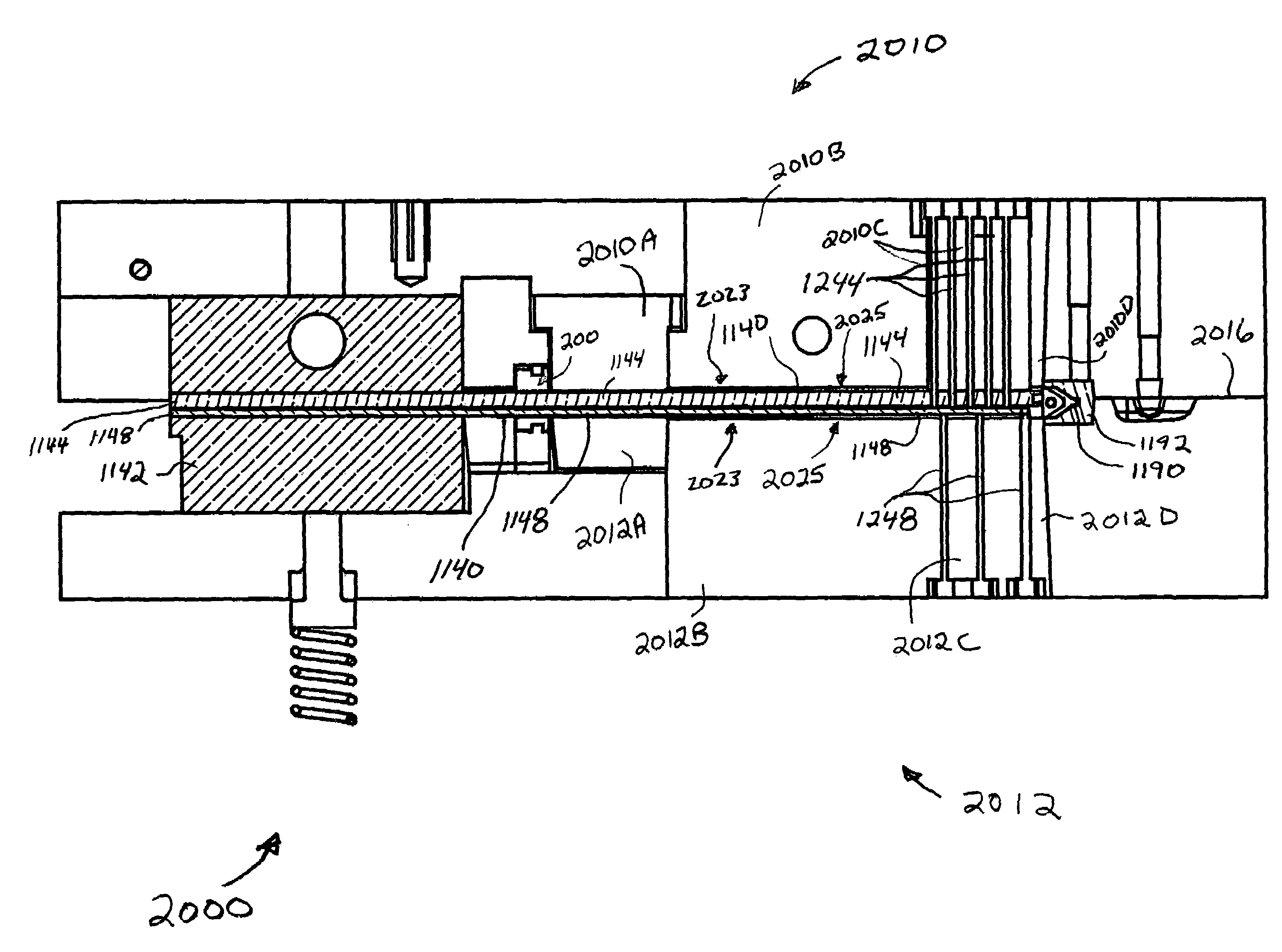
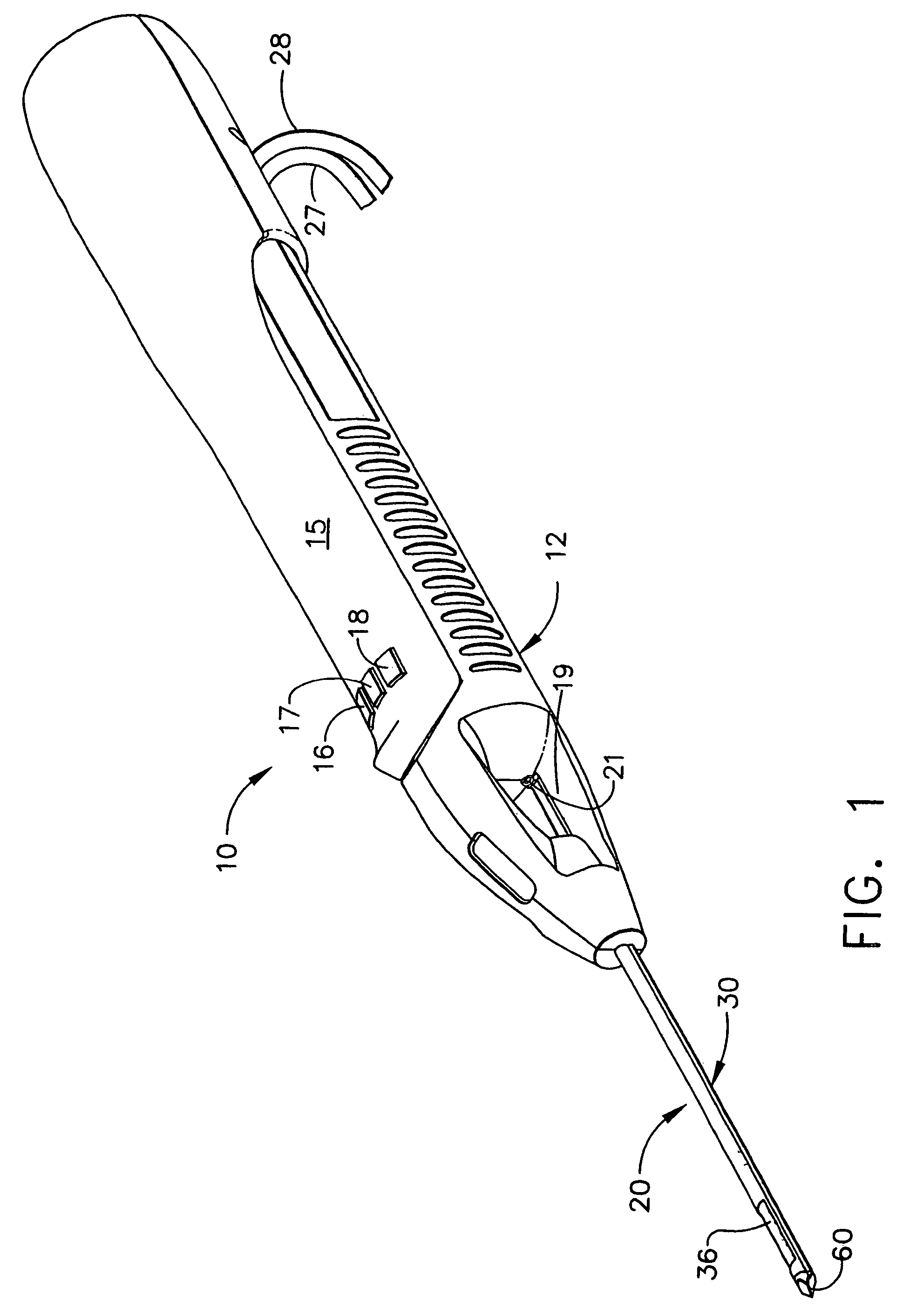
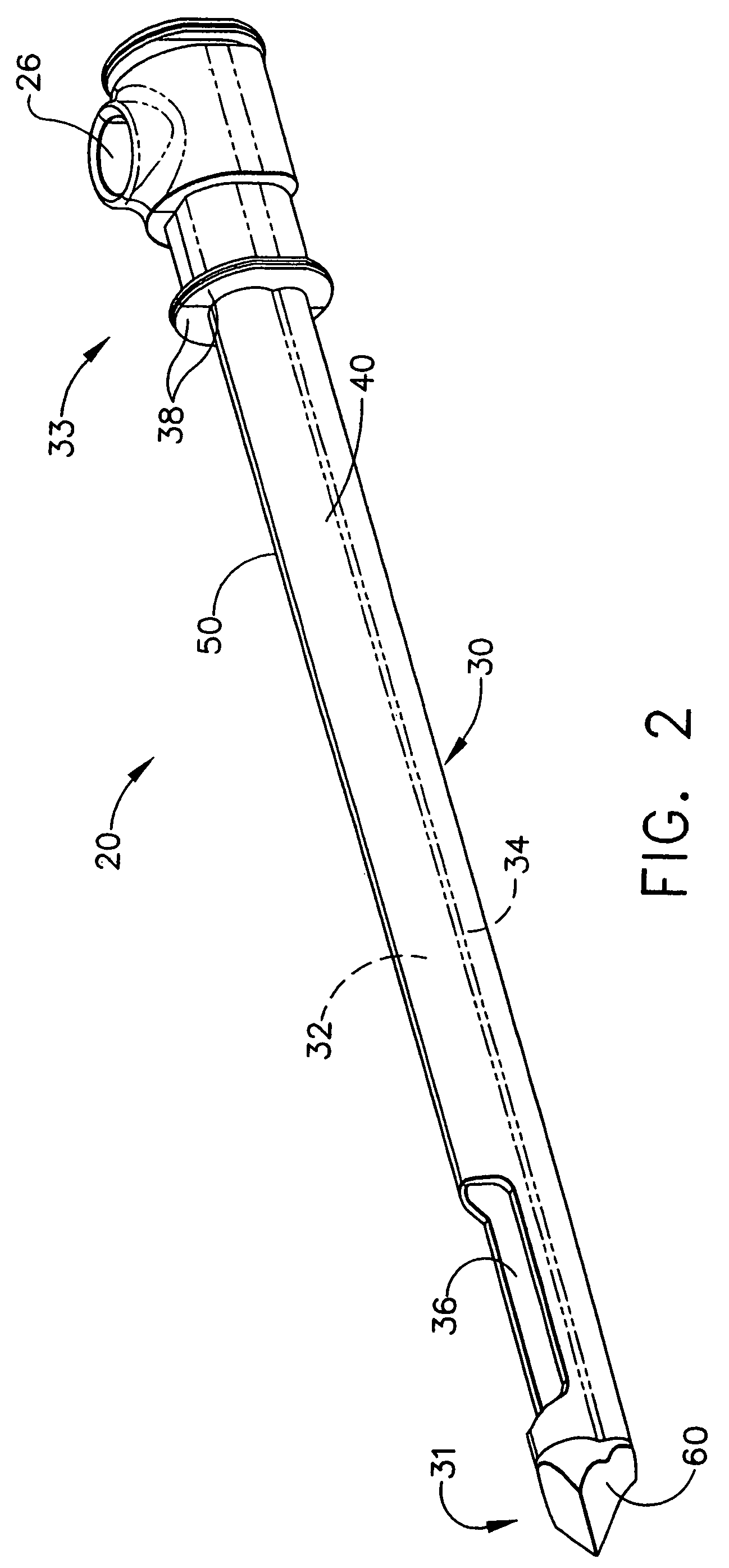
[0024]FIGS. 1-6 illustrate a biopsy device according to U.S. Pat. No. 6,626,849. FIGS. 7-12 illustrate embodiments of a biopsy device and a mold for making a biopsy device according to the present invention.

[0025]FIG. 1 shows a hand-held vacuum assisted biopsy device 10 comprising a needle assembly 20 and a holster 15, as described in U.S. Pat. No. 6,626,849. Needle assembly 20 is detachably connected to holster 15. Together they constitute a lightweight, ergonomically shaped, hand manipulatable portion referred to as handpiece 12. Since handpiece 12 is manipulated by the operator's hand rather than by an electromechanical arm, the operator may steer the handpiece 12 with great freedom towards the tissue mass of interest. The surgeon has tactile feedback while doing so and can thus, ascertain to a significant degree, the density and hardness of tissue being encountered. In addition, handpiece 12 may be held approximately parallel to the chest wall of a patient for obtaining tissue p...


PUM

PropertyMeasurementUnit
distanceaaaaaaaaaa
distanceaaaaaaaaaa
distanceaaaaaaaaaa

Abstract

A method for forming a needle assembly is provided. A distal portion of the needle can be formed of a first material which does not interfere with MRI imaging of a tissue receiving port disposed in the distal needle portion. A proximal needle portion can be formed of a second, different material, such as a metal. The proximal needle portion can provide strength and stiffness.

Description

[0001]This application cross-references and incorporates by reference the following application filed on even date herewith: “Biopsy Device” in the names of Tsonton et al., Ser. No. 10 / 808,078.FIELD OF THE INVENTION[0002]The present invention is related generally to biopsy devices, and more particularly, to an improved biopsy device for acquiring a tissue sample.BACKGROUND OF THE INVENTION[0003]The diagnosis and treatment of patients with cancerous tumors, pre-malignant conditions, and other disorders has long been an area of intense investigation. Non-invasive methods for examining tissue include palpation, thermography, PET, SPECT, Nuclear imaging, X-ray, MRI, CT, and ultrasound imaging. When the physician suspects that tissue may contain cancerous cells, a biopsy may be done either in an open procedure or in a percutaneous procedure. For an open procedure, a scalpel is used by the surgeon to create a large incision in the tissue in order to provide direct viewing and access to th...

Claims


Application Information

Patent Timeline
Patent Type & Authority Patents(United States)
IPC IPC(8): B29C45/14A61B10/02A61B5/055A61B10/00A61B19/00B21G1/08
CPCA61B10/0275A61B2017/00911A61B2019/5454A61B2090/3954
Inventor TSONTON, MARKTHOMPSONVANDER WENDE, JAMES W.
Owner DEVICOR MEDICAL PROD
Learn More