Phosphor converted light emitting device

a light-emitting device and phosphor-converting technology, applied in the direction of basic electric elements, chemistry apparatus and processes, and light-emitting compositions, can solve the problem that white light-emitting devices typically have undesirable color rendering properties

Active Publication Date: 2008-11-04
PHILIPS LUMILEDS LIGHTING CO LLC +1
View PDF13 Cites 35 Cited by
  • Summary
  • Abstract
  • Description
  • Claims
  • Application Information

AI Technical Summary

Problems solved by technology

Such white light devices typically have undesirable color rendering properties since the combined light is deficient in the red region of the visible light spectrum.

Method used


Image

  • Phosphor converted light emitting device
  • Phosphor converted light emitting device
  • Phosphor converted light emitting device

Examples


example i

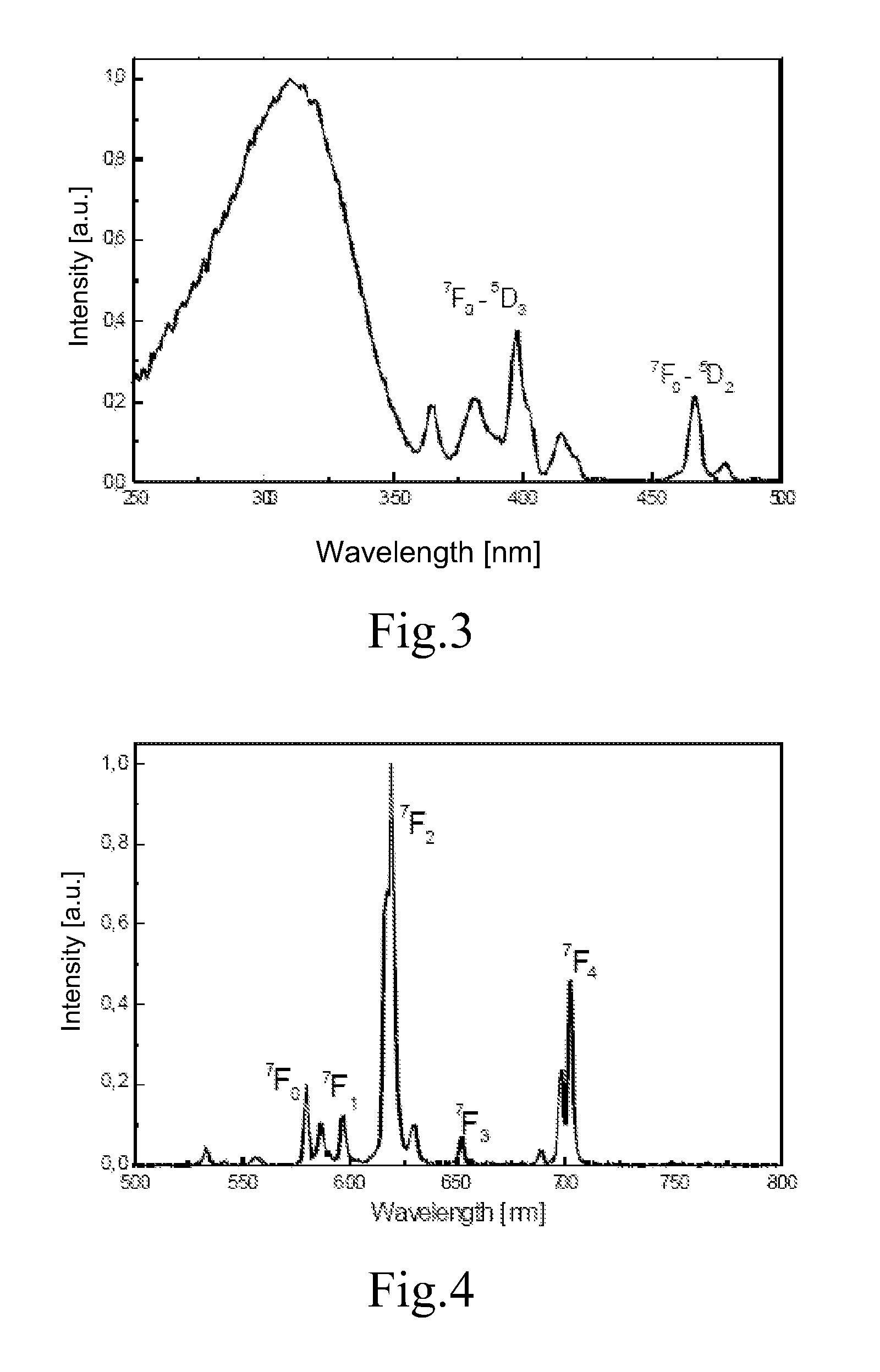
[0044]FIGS. 3 and 4 show the excitation and emission spectra of LaOCl:Eu. In FIG. 3, the maximum intensity in the wavelength range between 460 nm and 470 nm is about 21% of the maximum intensity in the wavelength range between 220 nm and 320 nm. In FIG. 4, the peak area in the wavelength range between 680 nm and 720 nm is 22% of the peak area in the wavelength range between 570 nm and 720 nm.

example ii

[0045]FIGS. 5 and 6 show the excitation and emission spectra of Sr3In2Ge3O12:Eu. In FIG. 5, the maximum intensity in the wavelength range between 460 nm and 470 nm is about 25% of the maximum intensity in the wavelength range between 220 nm and 320 nm. In FIG. 6, the peak area in the wavelength range between 680 nm and 720 nm is 25% of the peak area in the wavelength range between 570 nm and 720 nm.

example iii

[0046]FIGS. 7 and 8 show the excitation and emission spectra of Y2SiO5:Eu. In FIG. 7, the maximum intensity in the wavelength range between 460 nm and 470 nm is about 11% of the maximum intensity in the wavelength range between 220 nm and 320 nm. In FIG. 8, the peak area in the wavelength range between 680 nm and 720 nm is 21% of the peak area in the wavelength range between 570 nm and 720 nm.


PUM

PropertyMeasurementUnit
wavelengthaaaaaaaaaa

Abstract

A phosphor converted light emitting device includes a semiconductor structure comprising a light emitting layer disposed between an n-type region and a p-type region, the light emitting layer being configured to emit light having a first peak wavelength; a first phosphor configured to emit light having a second peak wavelength; and a second phosphor configured to emit light having a third peak wavelength. The second phosphor is an Eu3+-activated phosphor, configured such that in the excitation spectrum at 298K and 1.013 bar, a maximum intensity in a wavelength range between 460 nm and 470 nm is at least 5% of a maximum intensity in a wavelength range between 220 nm to 320 nm.

Description

BACKGROUND[0001]1. Field of Invention[0002]The present invention relates to phosphor-converted semiconductor light emitting devices.[0003]2. Description of Related Art[0004]Semiconductor light-emitting devices including light emitting diodes (LEDs), resonant cavity light emitting diodes (RCLEDs), vertical cavity laser diodes (VCSELs), and edge emitting lasers are among the most efficient light sources currently available. Materials systems currently of interest in the manufacture of high-brightness light emitting devices capable of operation across the visible spectrum include Group III-V semiconductors, particularly binary, ternary, and quaternary alloys of gallium, aluminum, indium, and nitrogen, also referred to as III-nitride materials. Typically, III-nitride light emitting devices are fabricated by epitaxially growing a stack of semiconductor layers of different compositions and dopant concentrations on a sapphire, silicon carbide, III-nitride, or other suitable substrate by me...

Claims


Application Information

Patent Timeline
Patent Type & Authority Patents(United States)
IPC IPC(8): H01L29/20H01L33/00H01L33/50
CPCC04B35/01C04B35/16C09K11/7792C09K11/7735C09K11/7788C04B2235/3208C04B2235/3213C04B2235/3222C04B2235/3224C04B2235/3286C04B2235/3287C04B2235/764C04B2235/9661C04B2235/3225C09K11/77922C09K11/77H05B33/14
Inventor MUELLER, GERD O.MUELLER-MACH, REGINA BJUESTEL, THOMASHUPPERTZ, PETRAWIECHERT, DETLEF UWEUHLICH, DOMINIK
Owner PHILIPS LUMILEDS LIGHTING CO LLC
Why Eureka
Try Eureka