Light source in optical transmission system, waveform shaper, optical pulse train generator, and optical reproduction system

a technology of optical transmission system and generator, applied in the field of light source in optical transmission system, waveform shaper, optical pulse train generator, optical reproduction system, can solve problems such as noise amplification phenomenon, and achieve the effect of less time fluctuation and less intensity fluctuation of optical pulses

Inactive Publication Date: 2008-11-04
FURUKAWA ELECTRIC CO LTD
View PDF7 Cites 12 Cited by
  • Summary
  • Abstract
  • Description
  • Claims
  • Application Information

AI Technical Summary

Benefits of technology

[0011]An optical pulse train generator of the present invention includes a dual-frequency beat light generating portion, a soliton shaper and a soliton compressor. In the conventional system shown in FIG. 1, dual-frequency beat signal light is lead to the adiabatic soliton compressor as it is. On the other hand, according to the present invention, as shown in FIG. 2, beat light is first subjected to conversion of a sin waveform into a soliton waveform in the soliton shaper before being input to the adiabatic soliton compressor. This consequently allows enhancement of a compression efficiency of the adiabatic soliton compression as well as suppression of SBS (Stimulated Brillouin scattering) in the compression fiber.
[0041]According to this embodiment, as the optical pulse generator is used as an optical clock pulse train generator, it is possible to obtain an optical clock pulse train with less intensity fluctuation of the optical pulse and less time fluctuation.

Problems solved by technology

However, it should be noted that interaction of remaining dispersion and dispersion slope and nonlinearity effect results in a noise amplification phenomenon.

Method used


Image

  • Light source in optical transmission system, waveform shaper, optical pulse train generator, and optical reproduction system
  • Light source in optical transmission system, waveform shaper, optical pulse train generator, and optical reproduction system
  • Light source in optical transmission system, waveform shaper, optical pulse train generator, and optical reproduction system

Examples


example 1

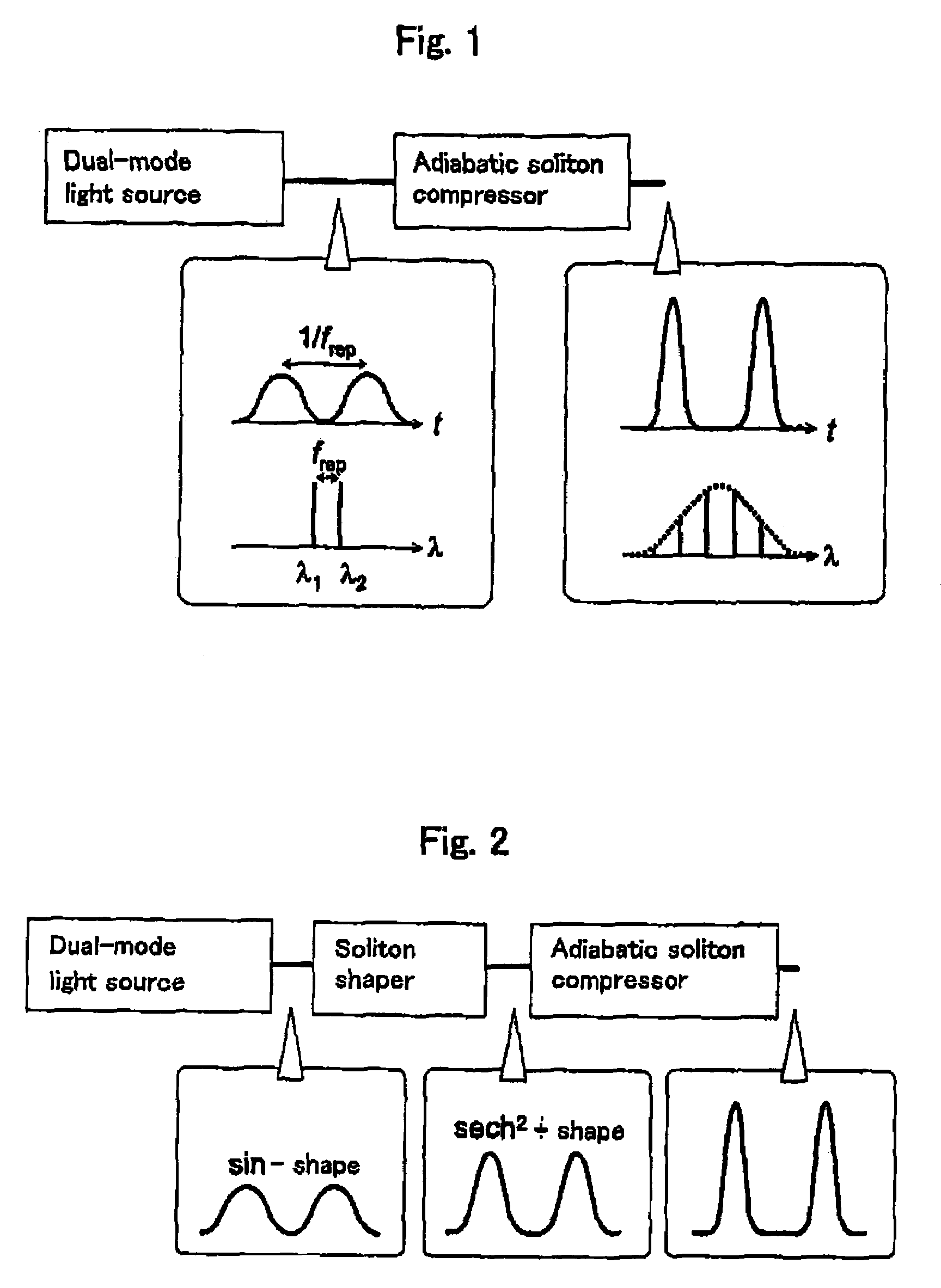
[0202]With use of a waveform shaper using a Raman amplifier in a CPF or a HNLF according to the present invention, it becomes possible to realize high-performance pulse train generator. The embodiment of this device is shown in FIG. 16. The device is composed of combination including a beat light generating portion, soliton converter and adiabatic soliton compressor. The light beat generating portion is a device for generating a sine wave signal. The beat light is then input to the soliton converter and subjected to soliton conversion. After soliton conversion, the light is input to the adiabatic soliton compressor and subjected low-noise pulse compression. Since the soliton converter and the soliton compressor are separately provided, optical transmission designs can be applied to the respective portions. This enables soliton compression of high quality and high efficiency. This soliton converter and the adiabatic soliton compressor may be provided with the aforementioned CPF or Ra...

example 2

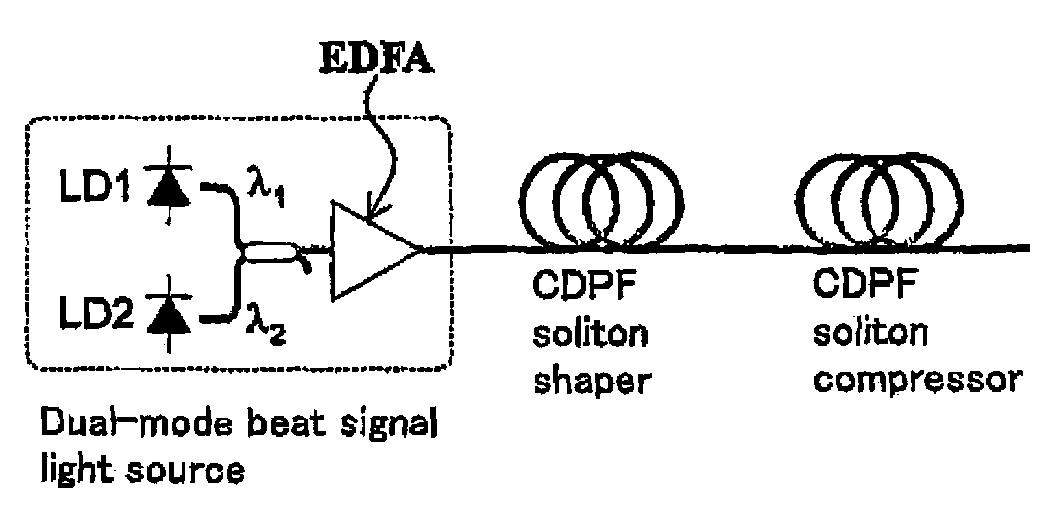
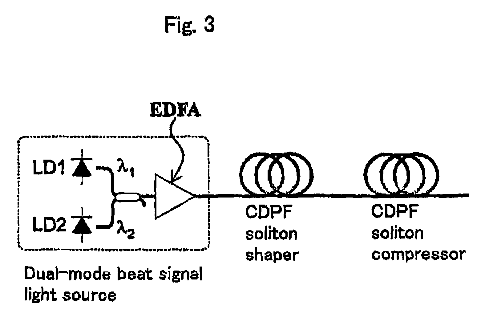
[0203]An optical pulse train generator using a CPF waveform shaper is shown in FIG. 17. This is an embodiment of the light source shown in FIG. 16, including a beat light generating portion composed of two CW-LDs, a soliton converter and a CPF soliton compressor. CW outputs from the two CW-LDs are combined to obtain beat light with a repetition frequency corresponding to the wavelength difference. In the first CPF, this beat light is converted into a soliton which is an optimal waveform for pulse compression and in the next CPF, the light is compressed. By use of the CPF soliton converter, beat light is not directly compressed but is converted into appropriate soliton before being compressed thereby making it possible to realize an ideal adiabatic soliton compression process.

[0204]The CPF includes three pairs of HNLF and SMF for each of soliton conversion and soliton compression. The nonlinearity coefficient of the HNLF is 24 l / W / km and its dispersion value is āˆ’0.8 ps / nm / km. Here, i...

example 3

[0209]Another embodiment of the present invention is a light source with a configuration shown in FIG. 20. This light source is an optical pulse train generator including a seed pulse generating portion for generating beat light or seed pulses from CW light by using an optical modulator; and a pulse waveform shaper for shortening time width.

[0210]A seed pulse is generated by a high-speed optical modulator, for example, a LiNbO3 optical modulator (LNM) or an electroabsorption semiconductor optical modulator. The high-speed optical modulator, for example, a LiNbO3 optical modulator (LNM) or an electroabsorption semiconductor optical modulator is driven by an external electric signal to easily generate an optical signal in synchronization with the electric signal. When an electric pulse signal is used as an electric signal, an optical pulse like the electric pulse signal is obtained. Needless to say, pulse repetition frequency or pulse time width are limited by a band of an electronic ...


PUM


Abstract

The present invention provides a pulse train generator comprising: a dual-frequency signal light source for generating a dual-frequency signal; a soliton shaper for soliton-shaping output light from the dual-frequency signal light source; and an adiabatic soliton compressor for performing adiabatic soliton compression on output light from the soliton shaper, and also provides a waveform shaper used in this pulse train generator, including a plurality of highly nonlinear optical transmission lines and a plurality of low-nonlinearity optical transmission lines which has a nonlinearity coefficient lower than that of the plurality of highly nonlinear optical transmission lines and which has a second-order dispersion value of which an absolute value is different from that of the plurality of highly nonlinear optical transmission lines. Further, the present invention provides a light source comprising a plurality of continuous light sources of which at least one oscillates in a multimode; a multiplexer for multiplexing output light from the continuous light sources; and a nonlinear phenomenon producer for producing a nonlinear phenomenon on output light from the multiplexer so as to suppress SBS (Stimulated Brillouin Scattering).

Description

TECHNICAL FIELD[0001]The present invention relates to a continuous light source in optical transmission systems, a controlling method of the light source, an apparatus applied to the pulse train generating technique and an optical regenerating system.BACKGROUND ART[0002]In the optical transmission system, as one of factors to limit the power of light input to the optical fiber, Stimulated Brillouin Scattering (SBS) occurs, which then causes backscattering of a part of the input power and this may adversely affect the transmission system. Conventionally, the technique of suppressing the SBS include: (1) electrically controlling a light source; and (2) optically controlling a light source. The technique (1) is electrical modulation such as frequency modulation, amplitude modulation and dither, which is disclosed in U.S. Pat. No. 5,329,396 December 1994 Fishman et al. The technique (2) relates to control of an optical spectrum using nonlinear phenomenon of an optical fiber, such as Cro...

Claims


Application Information

Patent Timeline
Patent Type & Authority Patents(United States)
IPC IPC(8): H04B10/04G02F1/35G02F1/365H01S5/062H04B10/18
CPCG02F1/3513G02F1/365H04B10/25077H04B10/291G02F2203/17G02F2203/26H01S5/0623
Inventor IGARASHI, KOJIEMORI, YOSHIHIROOGURI, ATSUSHINAMIKI, SHUASO, OSAMUTADAKUMA, MASATERU
Owner FURUKAWA ELECTRIC CO LTD
Why Eureka
Try Eureka