
Intergrated thin film subgap subpole structure for arbitrary gap pattern magnetic recording heads and method of making the same

a gap pattern and magnetic recording technology, applied in the field of magnetic recording heads, can solve the problems of amplitude modulation problems, inability to provide dedicated heads, dramatic affecting output signals, etc., and achieve the effect of improving efficiency and linearity of servo signals

Inactive Publication Date: 2008-11-11
ADVANCED RES
View PDF17 Cites 29 Cited by
  • Summary
  • Abstract
  • Description
  • Claims
  • Application Information

AI Technical Summary

Benefits of technology

"The present invention is about a new type of magnetic recording head that has low inductance and high efficiency. It is made using a special process that combines two major thin film planes. The head has a thin film subgap substrate structure and a magnetically permeable thin film that spans from one subpole to the other. The head can be used for writing or reading on high track density magnetic tape. The invention also describes a modified slanted gap structure that improves the efficiency and linearity of the servo signal. The technical effects of this invention are improved performance and reliability of magnetic recording devices."

Problems solved by technology

It is generally not feasible to provide a dedicated head or element for each data track, therefore, a multi-channel head(s) must move across the width of the tape, and each data channel head element accesses a large number of data tracks dedicated specifically to that head channel element.
The trend toward thinner and thinner magnetic tape layers causes amplitude modulation problems with this and other amplitude based heads.
That is, as the thickness of the magnetic layer decreases, normal variations on the surface represent a much larger percentage variation in the magnetic layer, which may dramatically affect the output signal.
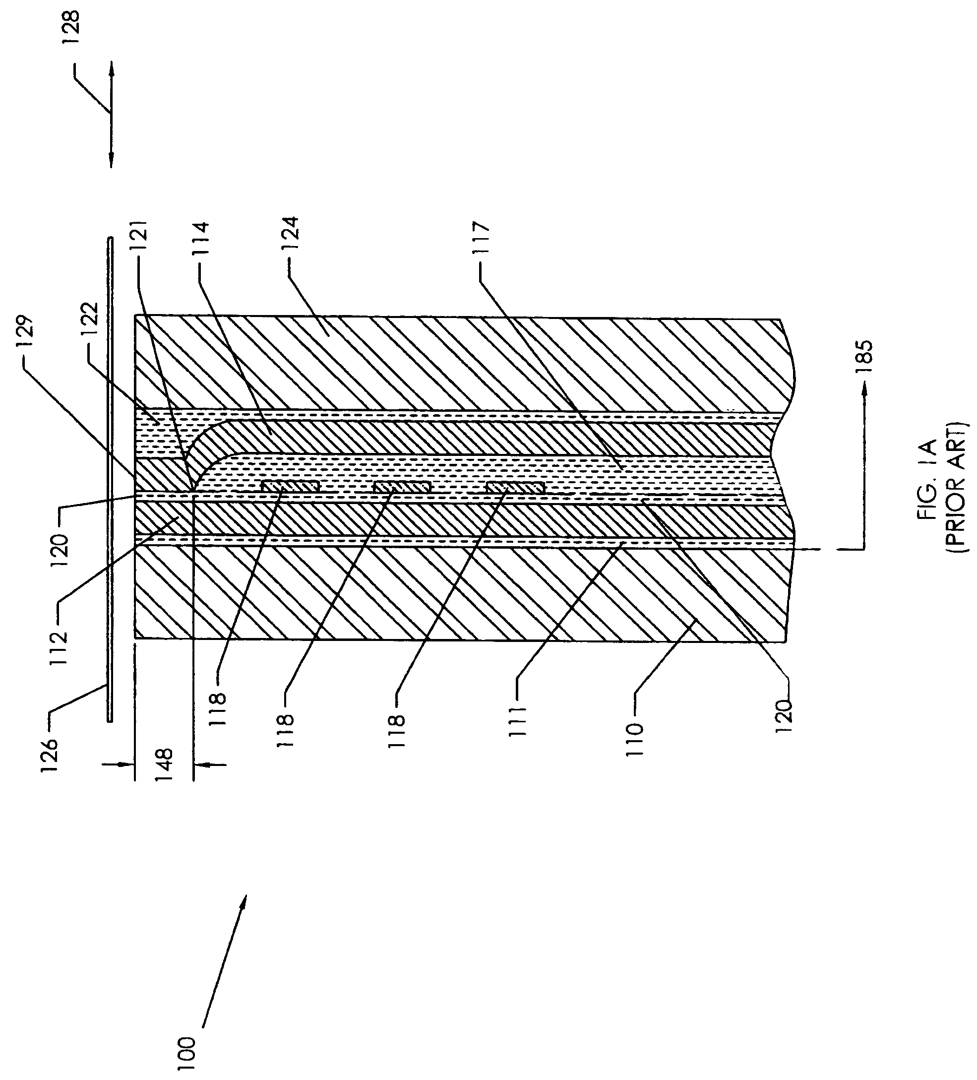
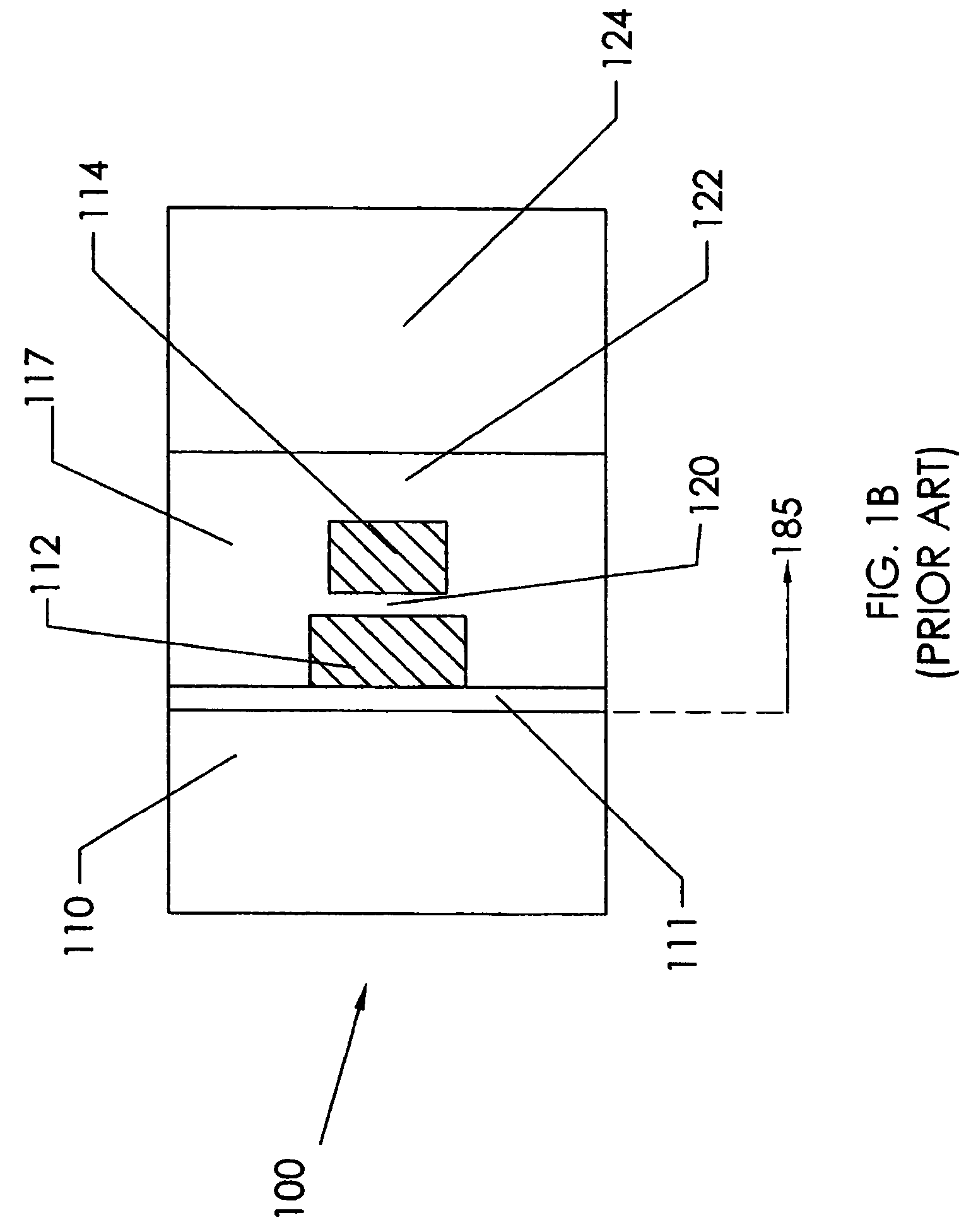
Indeed the first type, the Albrecht reference and the Dugas reference heads also use the HPP approach; however, those heads are not fully integrated and use a composite ferrite / ceramic substrate structure with a wound coil.
While this head solved the arbitrary gap limitation of the standard thin film head industry process, such a head is extremely difficult to manufacture and has not been produced commercially.
Hence, to date, pure thin film heads such as those that are made from VPP techniques are not suitable for timing-based heads, and those made from a fully integrated HPP technology are not seen as practical to produce such a magnetic head, each for different reasons.
Typically, VPP heads cannot be manufactured with a set of angled gaps as required for timing-based servo heads.
This makes it difficult, if not impossible, to make an angled gap, and the extension to multiple angled gaps in one head channel seems even more improbable.
However, it is not clear that the standard ion milling technique proposed to etch the gaps will result in good gap wall definition due to the well known aspect ratio considerations in such a milling technique.
Moreover, from a consideration of the layout of the coil upon the surface plane as shown in FIG. 2B, it may be difficult to have each write element 232 independently addressable with a separate coil.
Bringing coil terminations and leads out of the tape bearing plane of the head may pose a design issue for the head assembly.
This head has a rather large inductance and, therefore, relatively slow write current rise time.

Method used


Image

  • Intergrated thin film subgap subpole structure for arbitrary gap pattern magnetic recording heads and method of making the same
  • Intergrated thin film subgap subpole structure for arbitrary gap pattern magnetic recording heads and method of making the same
  • Intergrated thin film subgap subpole structure for arbitrary gap pattern magnetic recording heads and method of making the same

Examples


Embodiment Construction

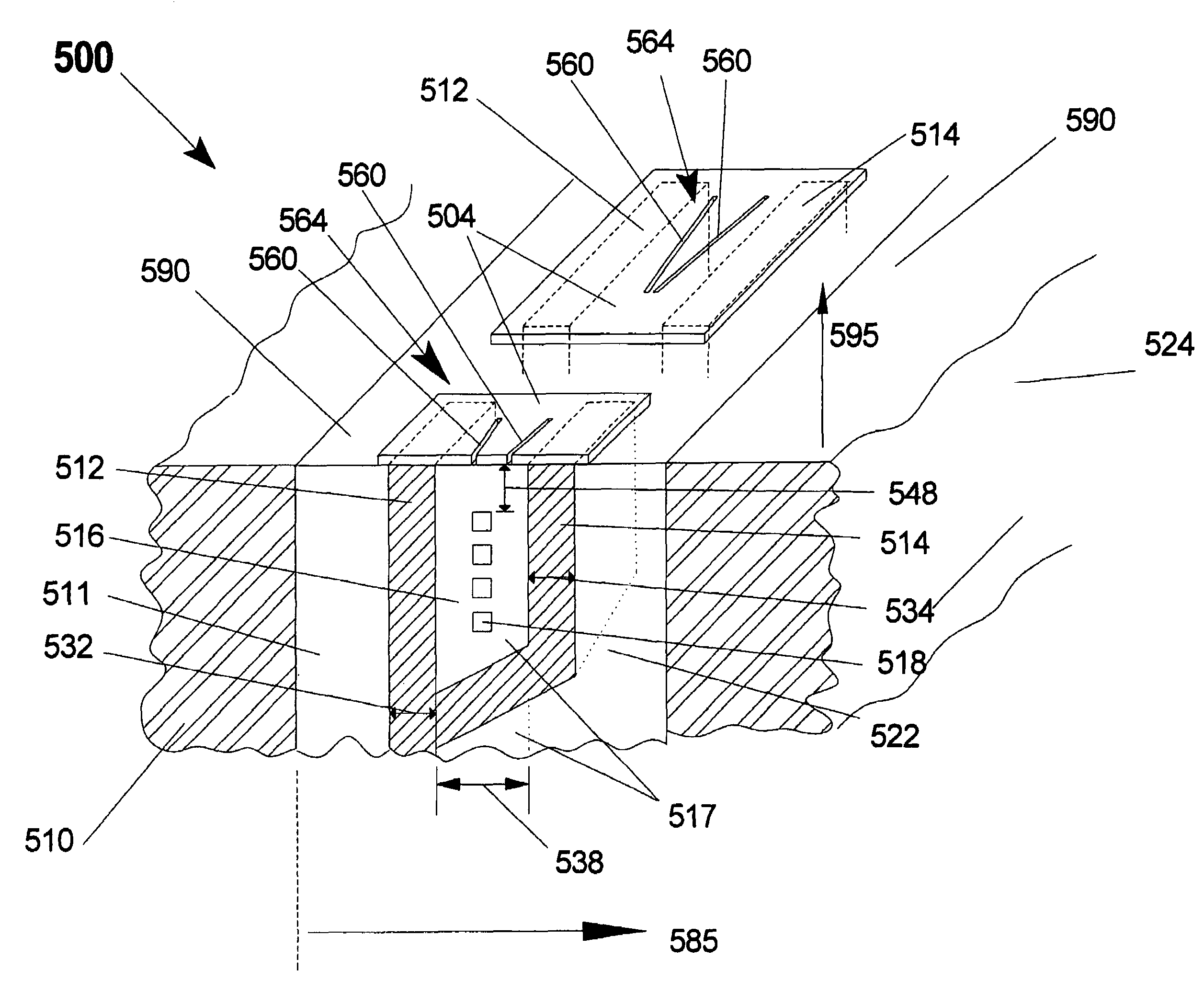
[0086]The present invention is a fully integrated arbitrary gap recording head which may contain single or multiple head elements and methods of making the same. The present invention enables the formation of a magnetic subgap and subpole row bar substrate from a wafer level process. This substrate is in turn used in a subsequent process in which an arbitrary gap pattern may be formed upon the subgap in-between the subpoles. The arbitrary gap pattern will be made in a magnetic thin film and will be driven by magnetic flux emulating from the subpoles. In various embodiments of the head of the present invention, the structure provides a head with operating efficiencies over prior-art heads and manufacturing efficiencies over prior art heads. For instance, a head of the present invention may provide a highly efficient multi-element recording head having a relatively high frequency response suitable for use as a servo write or a servo verify read head, and suitable for use as a data wri...


PUM

PropertyMeasurementUnit
widthaaaaaaaaaa
thicknessesaaaaaaaaaa
lengthaaaaaaaaaa

Abstract

An arbitrary gap thin film magnetic recording head is fabricated by forming a substrate based on traditional vertical planar thin film head wafer technology which is designed to produce an integrated subgap and subpole substrate structure. The recording head includes a pair of magnetically permeable thin film subpoles, separated by a low permeability subgap structure. An electrically conductive coil may be embedded, in part, within the subgap structure. Thus, the subpoles and subgap structure form part of a magnetic circuit. A highly permeable magnetic surface film spans from one subpole to the other having one or more arbitrary gap patterns. That is, a surface thin film is deposited and patterned on the tape bearing surface of the head to optimize various element configurations, gap patterns and head-to-tape medium contact.

Description

FIELD OF THE INVENTION[0001]This invention relates generally to magnetic recording heads and more particularly to head designs for the manufacture of heads with arbitrary shaped gaps used in high density tape data storage systems where such data storage systems may require complex arbitrary gap structures as in the case of servo format heads, advanced servo heads to enable patterns for the future or advanced angled gap write heads as in the case of azimuthal recording schemes.BACKGROUND OF THE INVENTION[0002]While a variety of data storage mediums are available, magnetic tape remains a preferred technology for economically storing large amounts of data. To facilitate the efficient use of this particular magnetic medium, magnetic tape is widely used in so-called multi-channel, linear tape format in which a plurality of servo and data tracks extend in the longitudinal direction of the tape. Magnetic track transitions embodying recorded data or servo information may be written into tra...

Claims


Application Information

Patent Timeline
Patent Type & Authority Patents(United States)
IPC IPC(8): G11B21/02G11B5/584G11B5/147G11B5/31
CPCG11B5/3103G11B5/3163G11B5/3173G11B5/3179G11B5/3183G11B5/584
Inventor DUGAS, MATTHEW P.SCHWARZ, THEODORE A.
Owner ADVANCED RES
Learn More