
Catalyst recovery method
a catalyst and recovery method technology, applied in the direction of machines/engines, separation processes, electric control, etc., can solve the problems of sox poisoning, long period or duration of execution of sox poisoning recovery control, and inability to easily release sulfur oxides (sox) absorbed in the nox storage reduction catalyst,
- Summary
- Abstract
- Description
- Claims
- Application Information
AI Technical Summary
Benefits of technology
Problems solved by technology
Method used
Image

Examples
Embodiment Construction
[0039]Now, preferred embodiments of the present invention will be described below in detail while referring to the accompanying drawings.
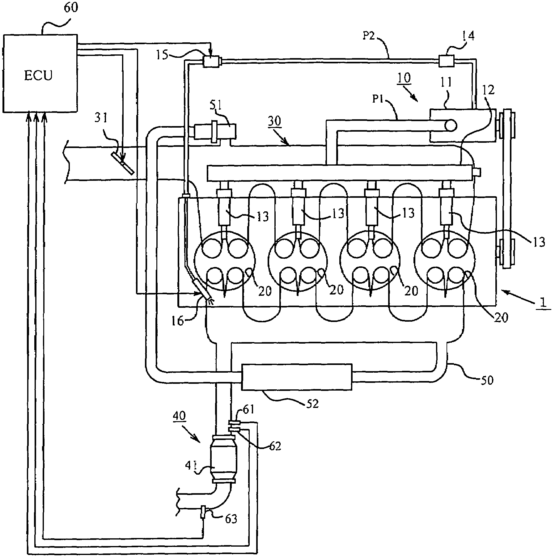
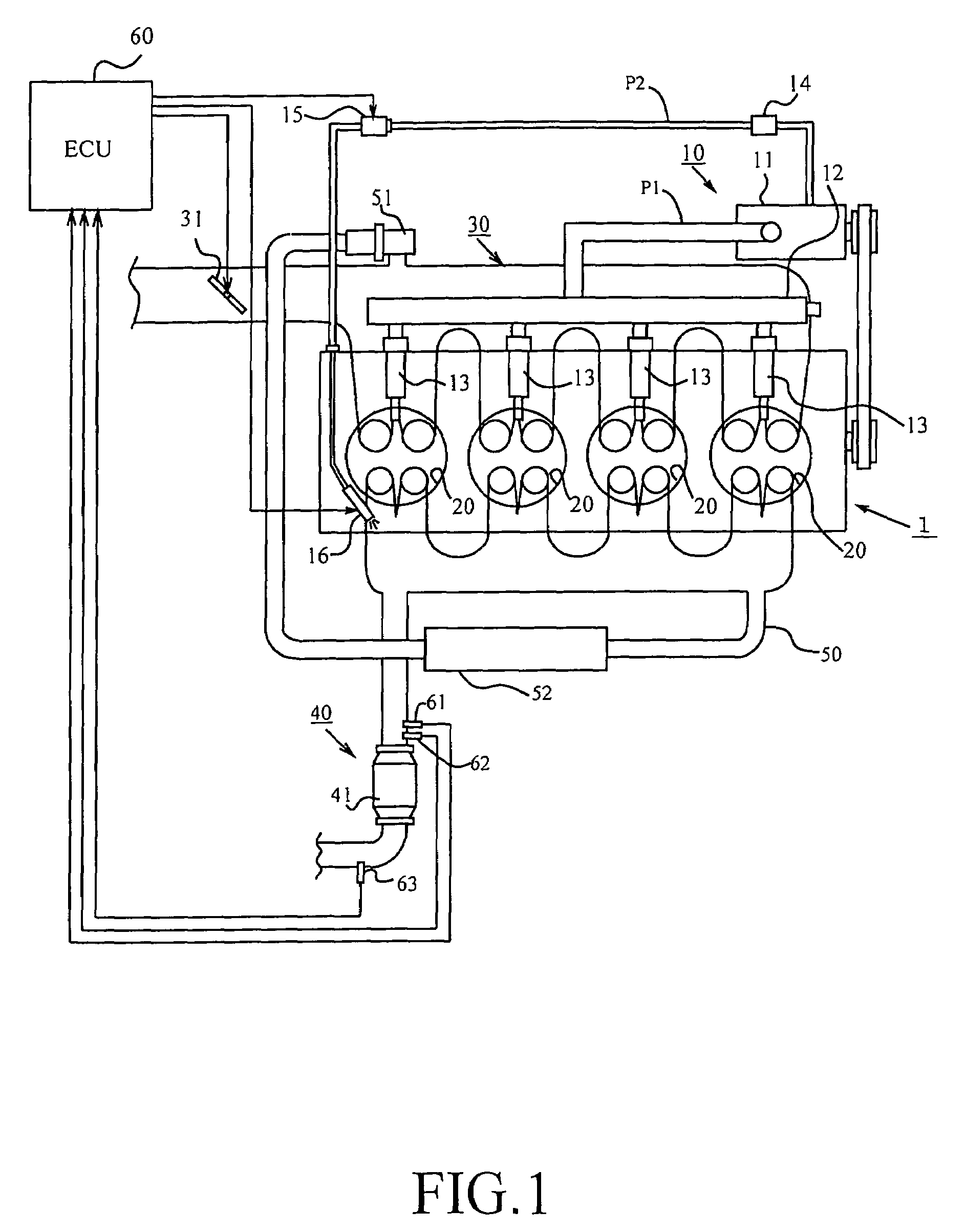
[0040]FIG. 1 is a view that illustrates the schematic construction of an internal combustion engine to which the present invention is applied. The internal combustion engine, generally designated at reference numeral 1 in FIG. 1, is an in-line four-cylinder diesel engine which includes, as its major components, a fuel supply system 10, a combustion chamber 20 defined in each cylinder, an intake system 30, an exhaust system 40, etc.
[0041]The fuel supply system 10 includes a fuel supply pump 11, a common rail 12, fuel injection valves 13, a shutoff valve 14, a metering valve 15, a reducing agent addition valve 16, an engine fuel passage P1, a fuel addition passage P2, etc.
[0042]The fuel supply pump 11 serves to draw up fuel from a fuel tank (not shown) and supply it to the common rail 12 through the engine fuel passage P1 while pressurizing the fuel ...
PUM
 Abstract
Description
Claims
Application Information