Amplifier circuit with reduced temperature dependence of the gain

a technology of temperature dependence and amplifier circuit, which is applied in the direction of negative-feedback circuit arrangement, low-noise amplifier, amplifier combination, etc., can solve the problems of increasing the current consumption of the amplifier circuit, undesirable or too large variation in some applications, and the amplifier circuit's gain fluctuation, so as to reduce the current consumption of the circuit in which the inventive amplifier circuit is employed, the effect of reducing temperature dependen

Inactive Publication Date: 2008-11-25
INFINEON TECH AG
View PDF2 Cites 5 Cited by
  • Summary
  • Abstract
  • Description
  • Claims
  • Application Information

AI Technical Summary

Benefits of technology

[0022]It is an object of at least some embodiments of the present invention to provide an amplifier circuit in which the gain temperature dependence is reduced.
[0024]One idea of embodiments of the present invention is to switch an element the impedance of which varies depending on the ambient temperature into a feedback path of an amplifier circuit, so that the variation of the gain depending on the temperature is reduced. Thus, feedback of an amplifier output signal to a control terminal of an amplifier circuit, at which the gain is adjusted, can be changed depending on the temperature. The feedback of the amplifier output signal may be influenced by the element with temperature-dependent impedance, so that the temperature dependence of the amplifier circuit is reduced.
[0026]Furthermore, the amplifier circuit with reduced temperature dependence according to an embodiment of the present invention avoids correctively regulating by a constant current source, which feeds the amplifier circuit. In such amplifier circuits, correctively regulating at increasing temperature serves to compensate for the temperature-induced decrease in gain. In this, the constant current has to be adjusted to a higher value with increasing temperature. According to an embodiment of the present invention, the high current consumption that would occur by this correctively regulating of the amplifier circuit at high temperatures can be avoided. With this, the current consumption of a circuit in which the inventive amplifier circuit is employed can be reduced.
[0027]Furthermore, by the reduction of the temperature dependence of the amplifier circuit, higher yield in mass production can be achieved. Here, a greater proportion of the amplifier circuits made in mass production has gain lying within the specified tolerances over a specified approved operating temperature range in which the amplifier circuit is to be employed in an electrical device. Thus, the yield in series production of the amplifier circuit is increased by the reduction of the temperature dependence. At the same time, this leads to lower fabrication costs.
[0028]Moreover, the reduction of the temperature dependence of the gain of the amplifier circuit in one embodiment of the present invention enables more flexible employment of the amplifier circuit. The amplifier circuit may be employed in applications designed for high ambient temperature, such as in the automobile industry, without downstream circuit elements having to compensate for the temperature-induced reduction of the gain.

Problems solved by technology

It is disadvantageous in the amplifier circuit shown in FIG. 4 that it is supplied with constant current, whereby the gain of the amplifier varies over the temperature.
This variation is undesirable or too great in some applications.
This would, however, be connected with increased current consumption of the amplifier circuit, which is disadvantageous particularly with battery-operated applications.

Method used


Image

  • Amplifier circuit with reduced temperature dependence of the gain
  • Amplifier circuit with reduced temperature dependence of the gain
  • Amplifier circuit with reduced temperature dependence of the gain

Examples


Embodiment Construction

[0034]In the subsequent description of the preferred embodiments, the same or similarly acting elements are provided with the same reference numerals. In particular, elements equal to or similarly acting as those from FIG. 4 are provided with the respective same reference numerals, and the following description is limited to illustrating the differences to the construction according to FIG. 4.

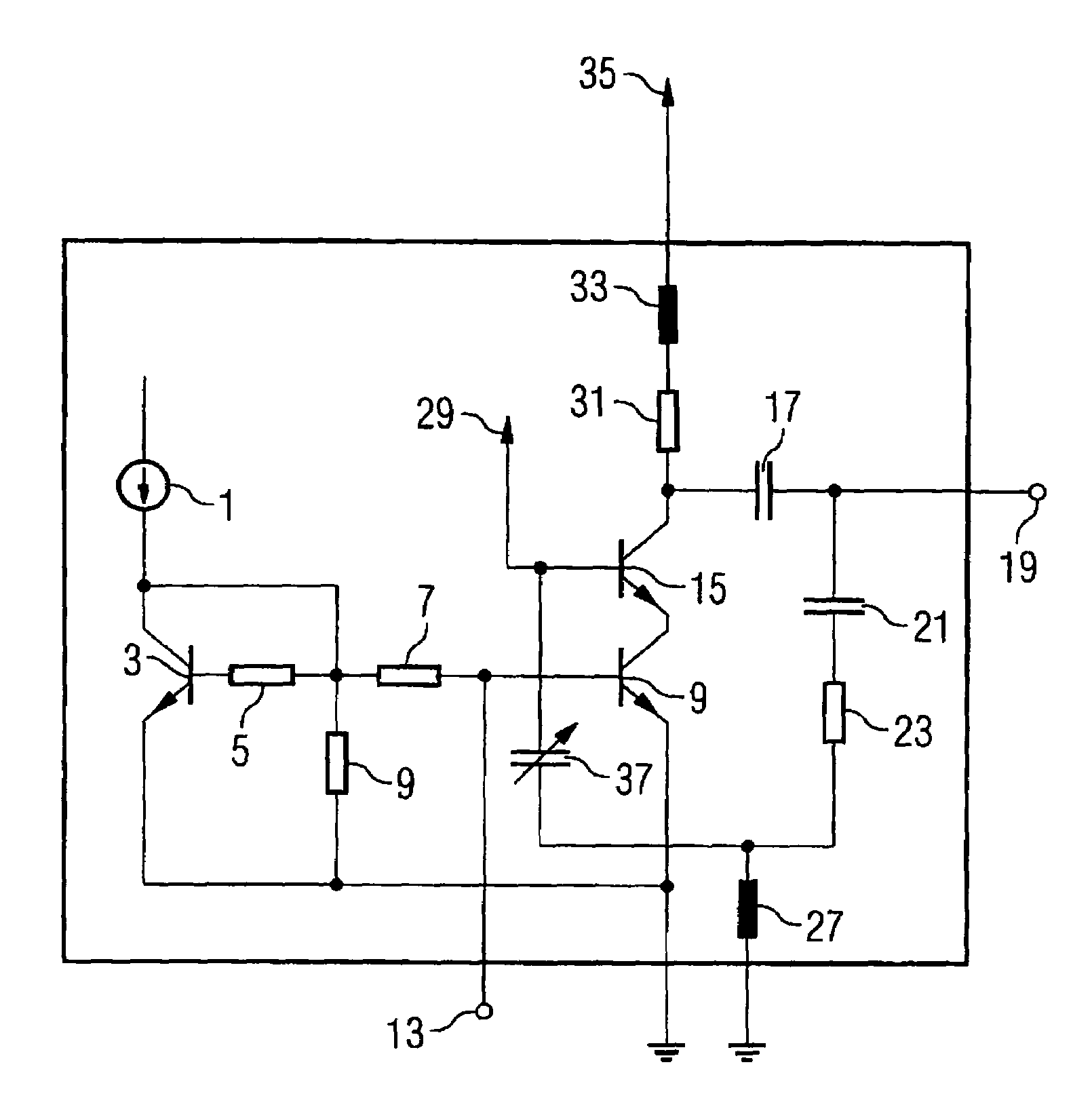
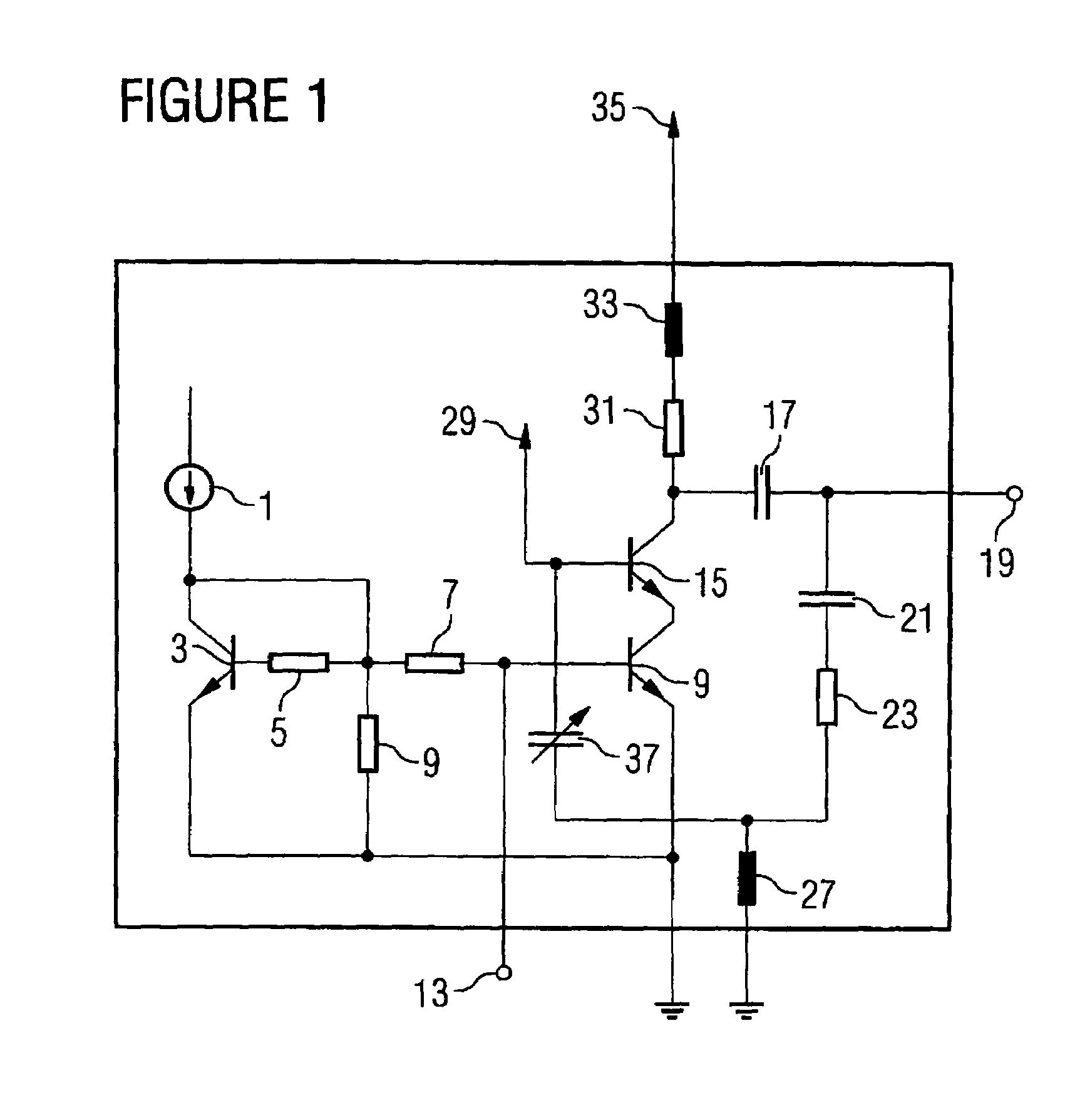
[0035]In contrast to the amplifier circuit shown in FIG. 4, in an amplifier circuit according to an embodiment of the present invention, which is shown in FIG. 1, the second feedback capacitor 25 is replaced by a capacitor 37 with temperature-dependent capacitance. The first feedback capacitor 21, the feedback resistor 23, and the capacitor 37 with temperature-dependent capacitance thus are connected in series between the output terminal 19 and the base of the output transistor 15.

[0036]For example, the capacitor with temperature-dependent capacitance 37 is designed so that its capacitance valu...


PUM


Abstract

An amplifier circuit includes an amplifier input, an amplifier output, a control terminal for adjusting a gain of the amplifier circuit, and a feedback path between the amplifier output and the control terminal, wherein a variable-impedance means, the impedance of which depends on a temperature so that a variation of the gain depending on the temperature is reduced, is connected in the feedback path.

Description

CROSS-REFERENCE TO RELATED APPLICATION[0001]This application claims priority from pending German Patent Application No. 102005007876.1, which was filed on Feb. 21, 2005, and is incorporated herein by reference in its entirety.BACKGROUND OF THE INVENTION[0002]1. Field of the Invention[0003]The present invention relates to an amplifier circuit with a feedback path.[0004]2. Description of the Related Art[0005]Amplifiers are increasingly used in environments with high temperature fluctuations. For example, the specified temperature ranges for amplifier circuits employed in the automobile area are between −40° C. and 125° C. Here, amplifier circuits exhibiting constant amplification behavior over a great temperature range are required.[0006]Frequently, so-called low-noise amplifiers or LNAs are employed as amplifiers. These LNAs have reduced noise behavior, which is why they are able to amplify signals, without significantly increasing the noise portion of the signals.[0007]FIG. 4 shows ...

Claims


Application Information

Patent Timeline
Patent Type & Authority Patents(United States)
IPC IPC(8): H03F1/22
CPCH03F1/302H03F1/34H03F2200/294H03F2200/372
Inventor MINICHSHOFER, JUERGEN
Owner INFINEON TECH AG
Why Eureka
Try Eureka