Quantum optical transmission device and quantum optical generator device therefor
a quantum optical generator and transmission device technology, applied in the direction of digital transmission, secret communication, securing communication, etc., can solve the problems of large-scale devices and high stability, not a simple quantum light source, and difficulty in beam splitting accurate 50:50
- Summary
- Abstract
- Description
- Claims
- Application Information
AI Technical Summary
Benefits of technology
Problems solved by technology
Method used
Image
Examples
first embodiment
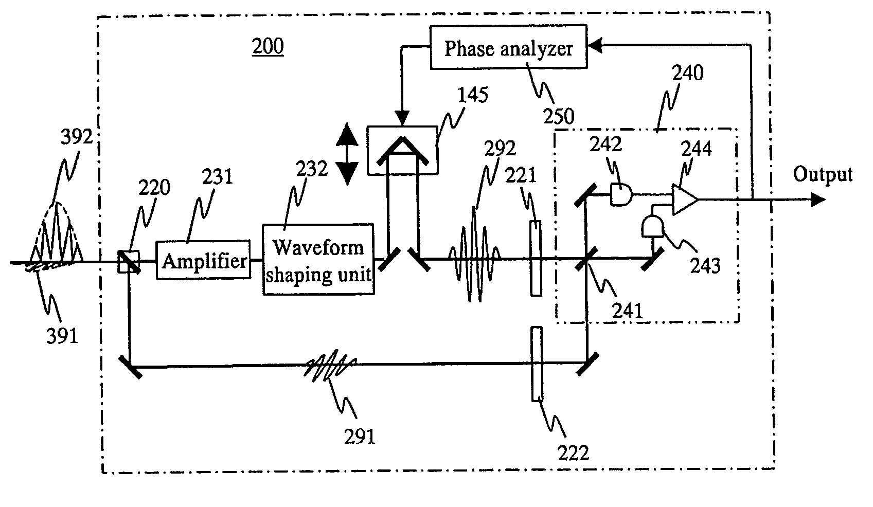
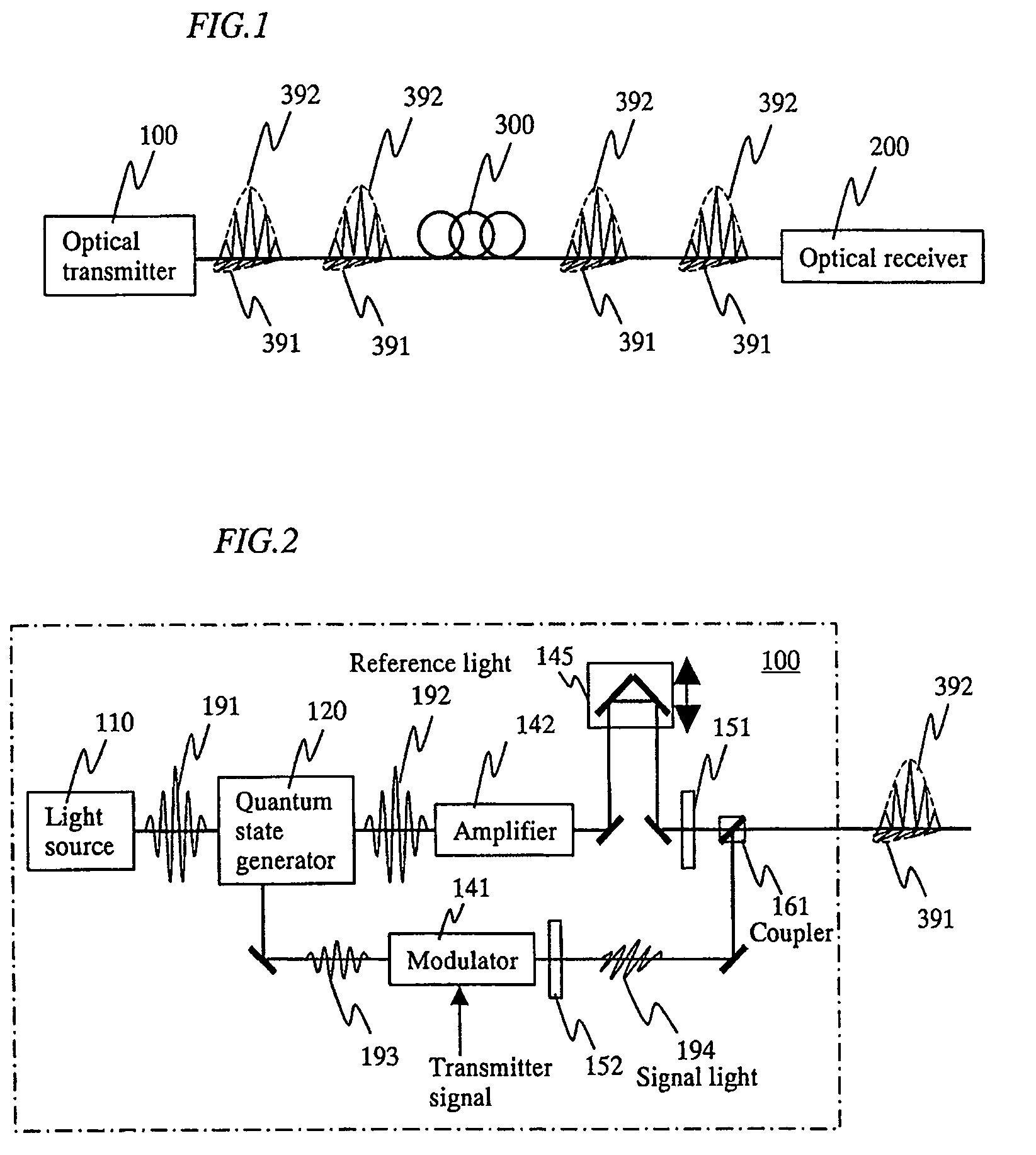
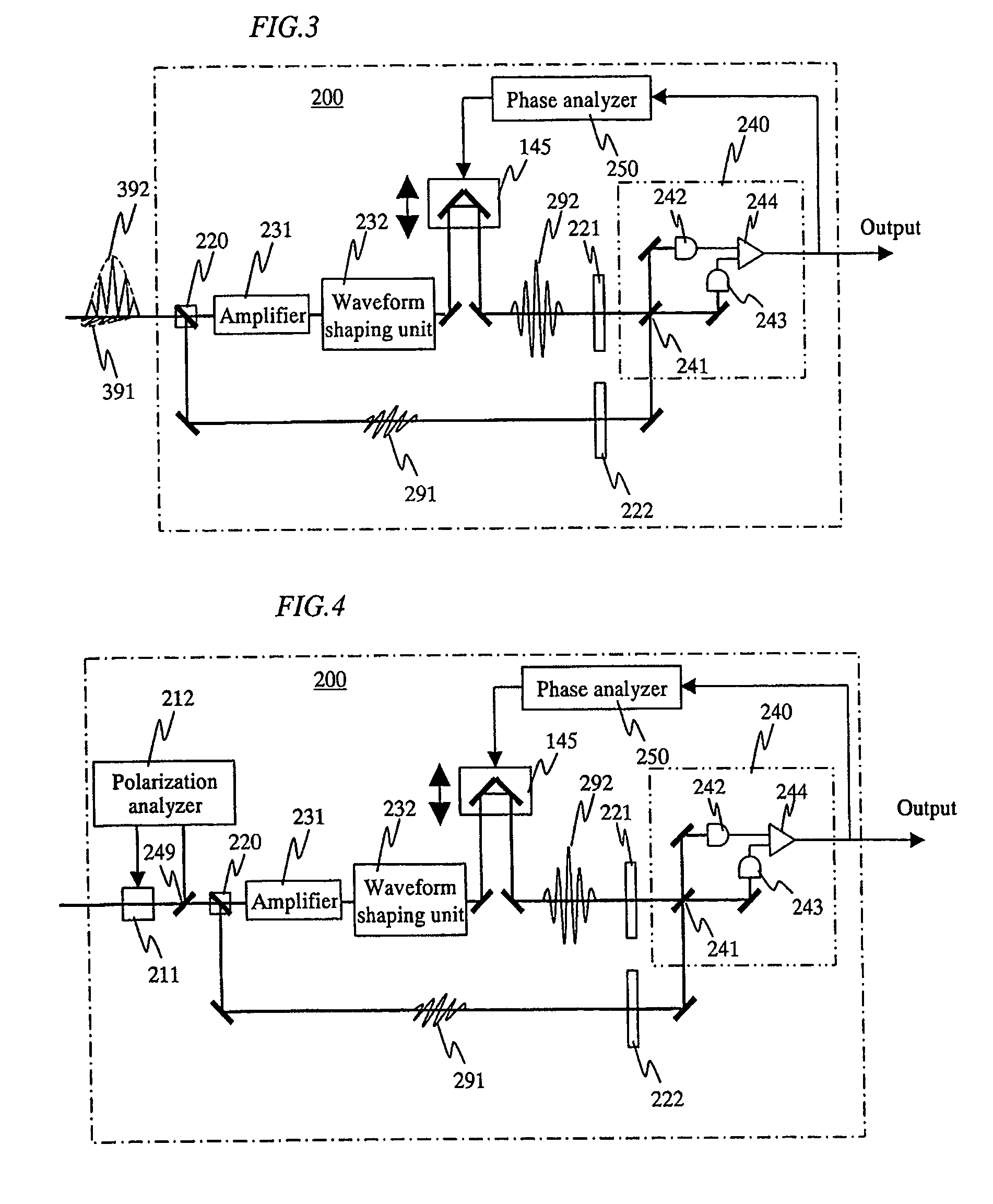
[0041]FIG. 1 is a diagram showing a system structure according to one of basic configurations of the present invention. A signal light 391 and a reference light 392 which have been outputted from an optical transmitter 100 to an optical fiber 300 are temporally superimposed on each other with the orthogonal polarization, and then transmitted to an optical receiver 200. The signal light 391 and the reference light 392 are generated with an identical light source as a seed light, and transmitted while being temporally superimposed on each other by the orthogonal polarization. Therefore, those phases are synchronous with each other when those signals are detected by the optical receiver 200.
[0042]When a pulsed light is propagated in an optical fiber at a long distance, the pulse is generally spread because of the fiber dispersion. However, when the pulsed light is propagated as a soliton, the pulsed light can be exceptionally propagated while maintaining the pulse width. In the quantum...
second embodiment
[0054]Subsequently, a description will be given in more detail of an embodiment of the quantum state generator 120 according to the present invention.
[0055]FIG. 8 is a block diagram showing a quantum state generator 120 according to a first structural example of the present invention. The pump light 1 is inputted to the polarizing beam splitter 11. The polarization of the pulsed pump light 1 is adjusted to a transparent direction of the polarizing beam splitter 11 (p-polarization) in advance. The transmitted pump light 1 passes through a Faraday rotator 26, the polarization rotates by 45°, and the polarization is adjusted by a λ / 2 waveplate 21. Here the Faraday rotator 26 and the λ / 2 waveplate 21 could be interchanged in place with each other. Thereafter, the pump light 1 is focused by a collimator lens 61 and then inputted to a short polarization maintaining optical fiber 36. The input light to the fiber 36 is adjusted by the λ / 2 waveplate 21 so that the intensities of the componen...
third embodiment
[0064]FIG. 11 is a diagram showing an example of a transmitter 100 in the case where the squeezed light that has been generated by the quantum state generator 120 described in the second embodiment is transformed into a signal light to conduct optical communication. In this example, the quantum state generator 120 described with reference to FIG. 8 is used. The pump light that has been outputted from the pump light source 110 passes through an isolator 213 and a λ / 2 waveplate 221, and then is inputted to a polarizing beam splitter 231 with P-polarization. The pump light 1 that has passed through the polarizing beam splitter 231 passes through a Faraday rotator 212 that rotates the polarization by 45°, and passes through a λ / 2 waveplate 222 to provide a P-polarized light. The pump light 1 is inputted to the quantum state generator 120 described with reference to FIG. 8 to obtain the pump light 2 that is outputted from the port 1, and the squeezed light 3 from the port 2.
[0065]The squ...
PUM
 Abstract
Description
Claims
Application Information
 - R&D
- Intellectual Property
- Life Sciences
- Materials
- Tech Scout
- Unparalleled Data Quality
- Higher Quality Content
- 60% Fewer Hallucinations
Browse by: Latest US Patents, China's latest patents, Technical Efficacy Thesaurus, Application Domain, Technology Topic, Popular Technical Reports.
© 2025 PatSnap. All rights reserved.Legal|Privacy policy|Modern Slavery Act Transparency Statement|Sitemap|About US| Contact US: help@patsnap.com


