Automatic internal combustion engine stop device, internal combustion engine provided with the same and automatic internal combustion engine stop method

a technology of automatic internal combustion engine and stop device, which is applied in the direction of engine starter, ignition automatic control, electric control, etc., can solve the problems of prolonging the time required for engine start, waste of fuel, and affecting the performance of the engine, so as to achieve the effect of short tim

Active Publication Date: 2008-12-02
TOYOTA JIDOSHA KK +1
View PDF25 Cites 39 Cited by
  • Summary
  • Abstract
  • Description
  • Claims
  • Application Information

AI Technical Summary

Benefits of technology

[0028]In the process of properly setting a piston stop position by stopping an internal combustion engine after removing or reducing the load on the engine (e.g., electrical loads), it is possible to suppress acceleration of the internal combustion engine, and to thereby stop a piston at an appropriate position within a shortened period of time by retarding the ignition timing of an ignition plug when the loads are removed.
[0031]As described above, if the ignition operation of the ignition plug is stopped and if the fuel injection is cut off when the load on the internal combustion engine and the engine speed are constant, a piston is always stopped at a constant position. This makes it possible to stop the piston at that proper position where startability of the internal combustion engine is enhanced. In this case, mere removal or reduction of the loads acting against the engine may bring about a rapid increase in the speed of the internal combustion engine. This may result in deviation of the piston stop position or prolongation of the time required for the internal combustion engine to stop. Thus, in the above aspects, the output power of the internal combustion engine is decreased by retarding the ignition timing of the ignition plug substantially at the same time as removal or reduction of the loads acting against the internal combustion engine. The ignition timing retard amount is proportional to the amount by which the load on the internal combustion engine is reduced. In other words, if the load on the internal combustion engine is greatly reduced, the more rapidly the speed of the internal combustion engine tends to increase in proportion thereto. In this case, the ignition timing retard amount is also set large. By setting the retard amount in this manner, it is possible to proportionally reduce the power of the internal combustion engine with respect to the reduction amount in the load, whereby the change in the speed of the internal combustion engine can be suppressed even when the load is removed or reduced. Namely, the automatic stop operation can be executed when the speed of the internal combustion engine is stabilized, thereby making it possible to stop the internal combustion engine at a proper piston stop position within a shortened period of time.
[0033]As noted above, if the ignition operation of the ignition plug is stopped before the fuel supply is cut off in the internal combustion engine automatic stop operation, there exists no cylinder in which a residual air-fuel mixture is combusted (an expansion stroke is executed) after the internal combustion engine automatic stop operation is initiated. This makes it possible to properly set the piston stop position with an increased accuracy in the process of stopping the internal combustion engine, which improves a reliable startability of the internal combustion engine when restarting the engine.
[0035]The configuration is particularly effective for a port-injected internal combustion engine whose fuel injection valve is provided in an intake port. As described above, in case the piston stop position of an initial combustion target cylinder is located near a bottom dead center, a large quantity of air is present in the cylinder at a relatively high temperature, thus leaving a possibility that an air-fuel mixture may auto-ignite to cause a great deal of vibration. Furthermore, the time required for the internal combustion engine to start is prolonged because no fuel is supplied into the cylinder until the next intake stroke. Moreover, in a case where the piston stop position in the initial combustion target cylinder lies outside the vicinity of the bottom dead center, if the cylinder is in a stroke other than the intake stroke (any one of the compression, expansion and exhaust strokes), no fuel is supplied into the cylinder until the next intake stroke, as in the preceding case. This prolongs the time required for the internal combustion engine to start. Taking this into account, if the internal combustion engine is stopped such that the piston stop position of a cylinder in the intake stroke lies near the top dead center and if that cylinder is selected as the initial combustion target cylinder, it becomes possible to supply fuel into the cylinder substantially at the same moment as commencement of the restart operation, whereby initial combustion can be completed in the compression stroke and the expansion stroke just after the fuel supply. This makes it possible to start the internal combustion engine within an extremely short period of time, while avoiding generation of vibration which would otherwise occur by the self-ignition of the air-fuel mixture.
[0038]In a more specific example of the automatic stop device, there is provided a throttle control unit for reducing an intake air quantity by decreasing an opening degree of a throttle valve at the same time as the retarding operation of the ignition timing of the ignition plug is started by the ignition timing control unit. As such, if the intake air quantity is reduced together with the retard operation of the ignition timing, it becomes possible to promptly decrease the speed of the internal combustion engine to the automatic stop operation triggering speed, thereby shortening the time required for the automatic internal combustion engine stop control (the control of stopping the ignition operation of the ignition plug and cutting off the fuel supply) to start after the satisfaction of the automatic stop condition for the internal combustion engine. This makes it possible to stop the internal combustion engine at a proper piston stop position within a shorter period of time.
[0043]In the present invention, acceleration of the internal combustion engine is suppressed by retarding the ignition timing of the ignition plug upon removal of the loads and properly setting the retard amount of the ignition timing, as opposed to a case where the piston stop position is properly set by removing the loads (an electrical load and the like) acting against the internal combustion engine and then performing the internal combustion engine stop operation upon satisfaction of the internal combustion engine automatic stop condition. This allows the internal combustion engine automatic stop operation to be performed under a state that the speed of the internal combustion engine is stabilized, thereby making it possible to stop the internal combustion engine at a proper piston stop position within a shortened period of time. Thus, the task of restarting the internal combustion engine can be completed without generating a great deal of vibration and within a short period of time.

Problems solved by technology

When a motor vehicle stops at an intersection, for example, to wait for traffic lights to change in the course of running in an urban area, etc., the engine is left idling, which wastes fuel.
For instance, if the piston stop position is not proper, a great deal of vibration is generated at the time of restart, thus giving an uncomfortable feeling to a driver and other vehicle occupants, or the time required for an engine to start up is prolonged to such a level as to give a sense of discomfort (what is called a feeling of delayed start) to the driver.
There will now be described a cause of generation of such vibration and a cause of prolongation of the time required for engine start.
If the cylinder proceeds to a compression stroke after fuel supply is completed through the intake stroke, an air-fuel mixture may self-ignite, at which time a great deal of vibration is generated.
Thus, initial combustion cannot be brought about unless the compression and expansion strokes begin subsequent to the next intake stroke.
This prolongs the time required to start the engine.
Thus, initial combustion cannot be brought about unless the compression and expansion strokes begin subsequent to the next intake stroke.
This prolongs the time required to start the engine.
The above are the cause of generation of vibration and the cause of prolongation of the time required to start the engine.
However, it is not easy to properly set the piston stop position at the time of idling stop.
JP-A 2005-282434 and JP-A 2005-315202, however, the reverse rotation of the crankshaft may result in some adverse effects.
For example, because the camshaft is reversely rotated and auxiliary mechanical components are reversely driven along with the reverse rotation of the crankshaft, it is concerned that the loads acting on individual components become heavier, thus shortening their life span.
In an actual operating state of the engine, however, it is often the case that the engine is operating under a relatively heavy load, e.g., the operation of an air conditioner.
This leaves a possibility that the engine may be stopped within a short period of time (time “β” in FIG. 9) after execution of the ignition cut and the fuel cut.
For this reason, the piston stop position at the time of idling stop is deviated from the piston stop position available in case of the curve “I”, thus making it impossible to properly set the piston stop position.
Although the afore-mentioned automatic engine stop operation is directed to a case where an engine is automatically stopped by an idling stop control, the same issue may possibly be applied to a case that, in a so-called a “hybrid car” equipped with an engine and an electric motor for running and adapted to run with a drive power of one or both of the engine and the electric motor, the engine is automatically stopped during the running (the running is carried out only with the driving power of the electric motor or a regenerative operation is started).
Similarly to the above-described case, this may possibly result in deviation of the piston stop position or prolongation of the time required for the engine to stop.

Method used


Image

  • Automatic internal combustion engine stop device, internal combustion engine provided with the same and automatic internal combustion engine stop method
  • Automatic internal combustion engine stop device, internal combustion engine provided with the same and automatic internal combustion engine stop method
  • Automatic internal combustion engine stop device, internal combustion engine provided with the same and automatic internal combustion engine stop method

Examples


Embodiment Construction

[0053]Hereinafter, preferred embodiments of the present invention will be described with reference to the accompanying drawings. In the present embodiments, description will be given to an instance that the present invention is applied to a multi-cylinder (e.g., four-cylinder) gasoline engine installed in a vehicle.

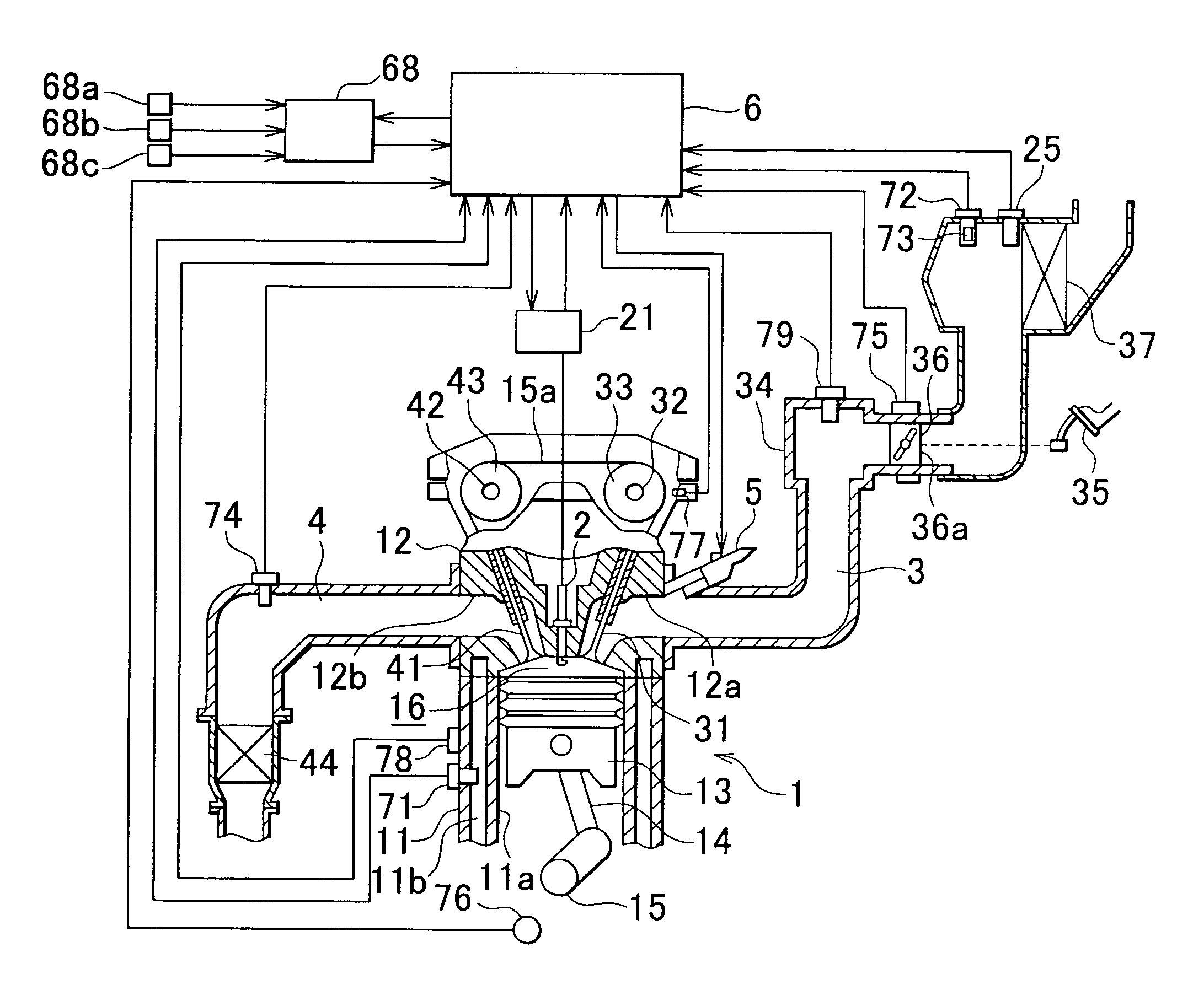
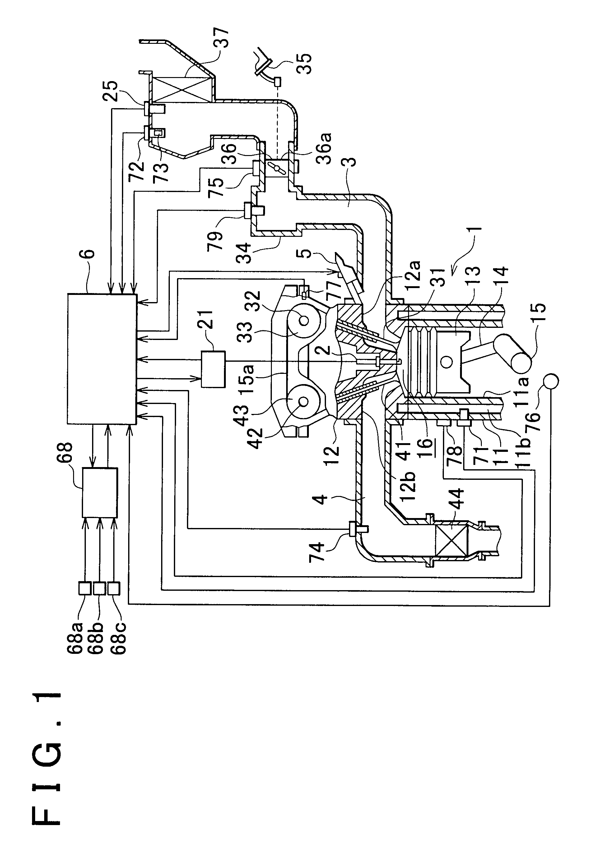
[0054]First, a schematic configuration of an engine (internal combustion engine) in accordance with an example embodiment of the present invention will be described with reference to FIG. 1. As shown in FIG. 1, the engine 1 of the present embodiment includes a cylinder block 11 and a cylinder head 12, the cylinder block 11 having cylinder bores 11a corresponding to four cylinders (only one cylinder bore is shown in FIG. 1). A piston 13 is slidably provided in each of the cylinder bores 11a and is connected through a connecting rod 14 to a crankshaft 15 serving as an output shaft of the engine 1. Further, there is defined in each of the cylinder bore 11a a combustion chamb...


PUM


Abstract

In an automatic stop device that automatically stops the operation of an internal combustion engine after a predetermined automatic stop condition is satisfied, a load acting on the engine is removed when the automatic stop condition is satisfied. When the automatic stop condition is satisfied, the between the magnitude of the load on the internal combustion engine before and after of the automatic stop condition is satisfied is determined, and an ignition timing retard amount of an ignition plug is decided such that the retard amount is increased as the difference becomes greater. The ignition timing is retarded by the retard amount substantially at the same moment as the load removing operation before the automatic stop control is initiated.

Description

INCORPORATION BY REFERENCE[0001]The disclosure of Japanese Patent Application No. 2006-052672 filed on Feb. 28, 2006 including the specification, drawings and abstract is incorporated herein by reference in its entirety.BACKGROUND OF THE INVENTION[0002]1. Field of the Invention[0003]The present invention relates to an automatic internal combustion engine stop device, an internal combustion engine provided with the same and an automatic internal combustion engine stop method; more particularly, to an improvement for optimizing a piston stop position in an automatic internal combustion engine stop device for automatically stopping an internal combustion engine (hereinafter simply referred to as “engine”) during an idling operation thereof, for instance.[0004]2. Description of the Related Art[0005]When a motor vehicle stops at an intersection, for example, to wait for traffic lights to change in the course of running in an urban area, etc., the engine is left idling, which wastes fuel....

Claims


Application Information

Patent Timeline
Patent Type & Authority Patents(United States)
IPC IPC(8): F02N17/00F02P5/00F02N99/00F02D17/00F02D29/02F02D41/04F02D41/06F02D43/00F02N15/00F02P5/15
CPCF02D17/04F02D41/042F02N11/0818F02P5/1502F02D2041/0095F02N19/005F02N99/006F02N2019/008Y02T10/46Y02T10/48Y02T10/40
Inventor TAKAHASHI, SHIGENORI
Owner TOYOTA JIDOSHA KK
Why Eureka
Try Eureka