Superconductive crossbar switch

a crossbar switch and superconducting technology, applied in pulse generators, instruments, pulse techniques, etc., can solve the problems of large parallel computing system, inability to meet all requirements, and large number of computing elements, etc., to achieve low power, low latency, and extensibility

Inactive Publication Date: 2008-12-02
BEDARD FERNAND D
View PDF9 Cites 9 Cited by
  • Summary
  • Abstract
  • Description
  • Claims
  • Application Information

AI Technical Summary

Benefits of technology

[0011]The present invention overcomes the above identified drawbacks of the prior switching circuits, as well as others, by providing a modular crossbar switch that is extendable in size, operates under low power with low latency, and detects and resolves conflicts that arise when two or more processors contend for the same memory port. The switch of the present invention is capable of interconnecting N computers or processors with M memories, or other processors or computers where N and M can be of the order of 1000 or more. One embodiment of the present invention is also modular, in that small crossbars can easily be extended to become very large ones, (e.g., 32×32 can grow into 1000×1000). In addition, if the computer data rate exceeds that of one channel, paralleling of channels is easily performed. The switch is also suitable for general communications network usage, as well.
[0015]In a further embodiment of the present invention, each output includes a summing device for summing output voltages or currents of the cells connected therewith, in order to accommodate the inputs and to render the matrix extendable in numbers of inputs and outputs.
[0019]In a further embodiment of the invention, a sensing apparatus is connected with each of the outputs for detecting simultaneous queries to cells of the respective groups of cells and for generating to the processors via the cells an indication of conflict from the simultaneous queries as well as resolving these conflicts while preventing further interference.

Problems solved by technology

Prior switching circuits possess certain inherent drawbacks that render them unsuitable for use with large numbers of computing elements.
As a result, they cannot meet all of the requirements set forth above for a massively parallel computing system.

Method used


Image

  • Superconductive crossbar switch
  • Superconductive crossbar switch
  • Superconductive crossbar switch

Examples


Embodiment Construction

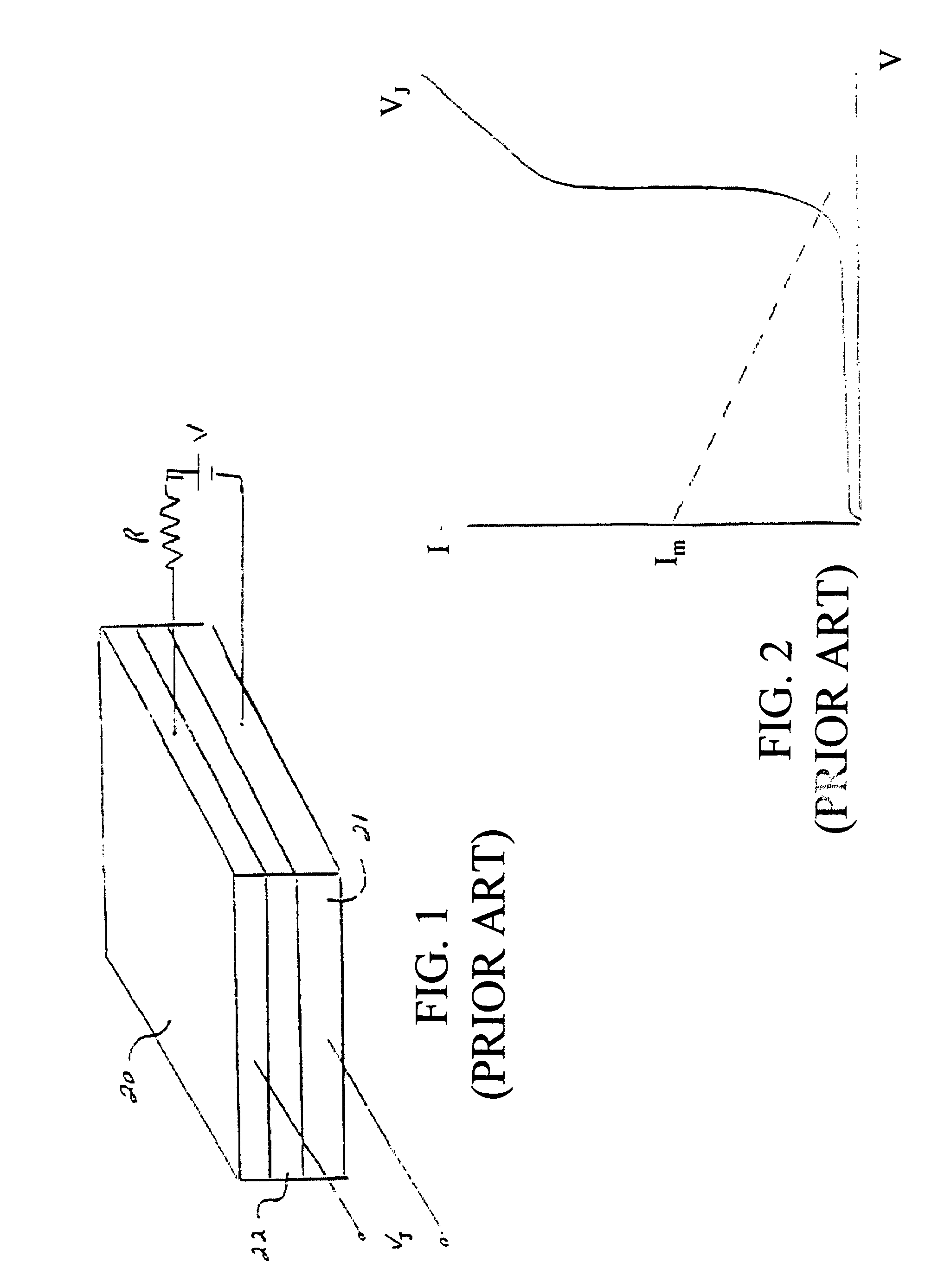
[0039]FIG. 1 illustrates a Josephson tunnel junction device known in the prior art. The Josephson tunnel junction device includes top and bottom layers 20, 21 of superconductor material sandwiching a thin insulating film 22. If a voltage V is applied between the top and bottom layers through a resistance R, there is a range of current in which zero resistance current up to Im, can be transported between the two elements.

[0040]FIG. 2 illustrates the behavior of the circuit current I as the input voltage V is increased for a representative resistance R, in the Josephson tunnel junction device shown in FIG. 1. The voltage Vj across the device will be zero until the device current exceeds Im, at which point the junction will switch to the voltage state consistent with the circuit load resistor R and the device's own voltage-current curve J, determined by the physics and manufacturing art.

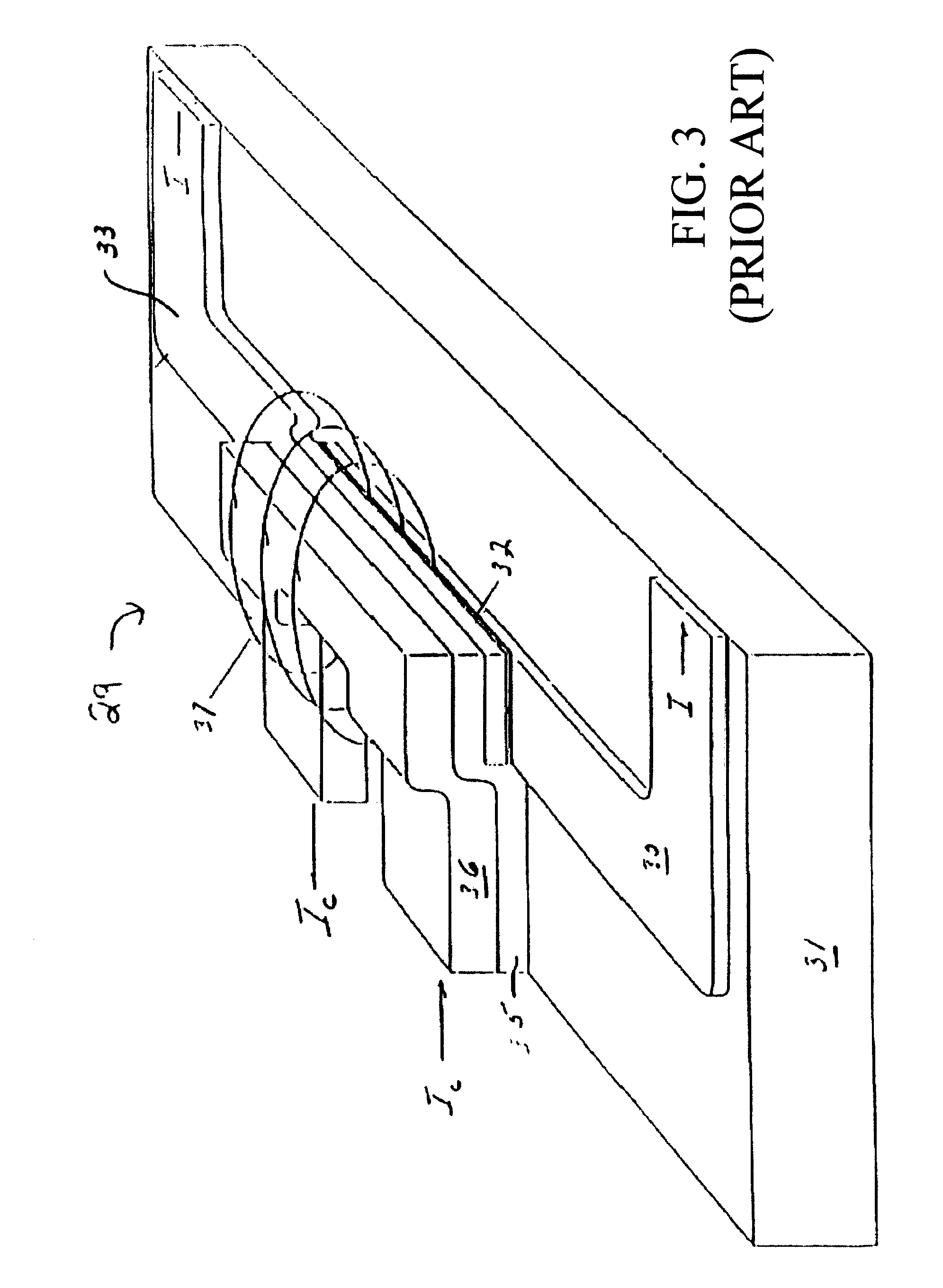
[0041]FIG. 3 illustrates a Josephson junction device 29 known in the prior art, in which switching o...


PUM


Abstract

A superconductor crossbar switch for connecting a plurality of inputs with a plurality of outputs, including a switching cell having an input, an output and a circuit for connecting the input with the output for bidirectionally transmitting data therebetween. The connection of the retaining and releasing circuitry of a plurality of cells enables the switch to simultaneously retain a selected cell or cells of a group of cells and disable the remaining cells of that group, whereby a subsequent query on a disabled cell is inoperative until the selected cell or cells is released. The crossbar switch is characterized by latency on the order of nanoseconds, a data rate per channel on the order of gigabits per second, essentially zero crosstalk, and detection of contention in nanoseconds or less and resolution of contention in nanoseconds or less.

Description

CROSS-REFERENCE TO RELATED APPLICATIONS[0001]This application is a continuation of U.S. application Ser. No. 10 / 200,115, filed on Jul. 23, 2002 now U.S. Pat No. 6,960,929, which, in turn, is based on and derives the benefit of U.S. Provisional Patent Application Ser. No. 60 / 306,880, filed on Jul. 23, 2001. The entire contents of Ser. No. 10 / 200,115 and Ser. No. 60 / 306,880 are incorporated herein by reference.[0002]This invention was made with government support of Job No. 768, of the National Security Agency. The government may have certain rights in this invention.BACKGROUND OF THE INVENTIONField of the Invention[0003]The present invention relates to superconductive switching devices, and in particular to a superconducting crossbar switch for bi-directionally connecting a plurality of inputs with a plurality of outputs.Background of the Technology[0004]Advances in high performance computing are being pursued in many different directions. The technology thrust has been directed towa...

Claims


Application Information

Patent Timeline
Patent Type & Authority Patents(United States)
IPC IPC(8): H03K17/92H01L39/22H03K17/00H03K19/195H04Q3/00H04Q3/52
CPCH03K17/92H04Q3/0004H04Q3/521H04Q2213/1302H04Q2213/1304H04Q2213/13305H04Q2213/1334H04Q2213/13341
Inventor BEDARD, FERNAND D.
Owner BEDARD FERNAND D
Why Eureka
Try Eureka