Control of an electrically heated pre-heating device for cold-starting internal combustion engines

a technology of pre-heating device and internal combustion engine, which is applied in the direction of engine starter, combustion air/fuel air treatment, machine/engine, etc., can solve the problems of incomplete combustion, high pressure gradient, and increase the time between fuel entering the combustion space and igniting, so as to improve the effect of existing cold start devices

Inactive Publication Date: 2008-12-16
DAIMLER AG
View PDF10 Cites 29 Cited by
  • Summary
  • Abstract
  • Description
  • Claims
  • Application Information

AI Technical Summary

Benefits of technology

[0012]Proceeding from the abovementioned prior art, it is the object of the invention to improve the effect of existing cold start devices by means of improved actuation.

Problems solved by technology

At low ambient air temperatures and consequently at low intake air temperatures, an insufficient post-compression temperature and hence an increasing ignition delay occur, in diesel engines in particular, so that the period between the fuel entering the combustion space and igniting becomes too long.
In addition, local over-enrichment, incomplete combustion and high pressure gradients occur at low intake temperatures as a result of sudden mixture conversion in the cylinder.
The results are greatly increased hydrocarbon emissions in the exhaust gas, knocking of the diesel engine and the disadvantages resulting from this such as severe environmental pollution and increased loading of the powertrain parts.
Since manufacturers of these units use increasingly high-powered direct injection diesel engines with a small swept volume which only deploy their full power at full charge air pressure, problems occur when cold starting in regions at relatively high altitude, since no charge air pressure is initially present.
If such an engine is started at an altitude of for example 3000 m above sea level and at −15° C., pre-heating devices known today are not sufficient unless the engine is brought up to operating temperature by the coolant temperature by means of a complex auxiliary heating system.

Method used


Image

  • Control of an electrically heated pre-heating device for cold-starting internal combustion engines
  • Control of an electrically heated pre-heating device for cold-starting internal combustion engines
  • Control of an electrically heated pre-heating device for cold-starting internal combustion engines

Examples


Embodiment Construction

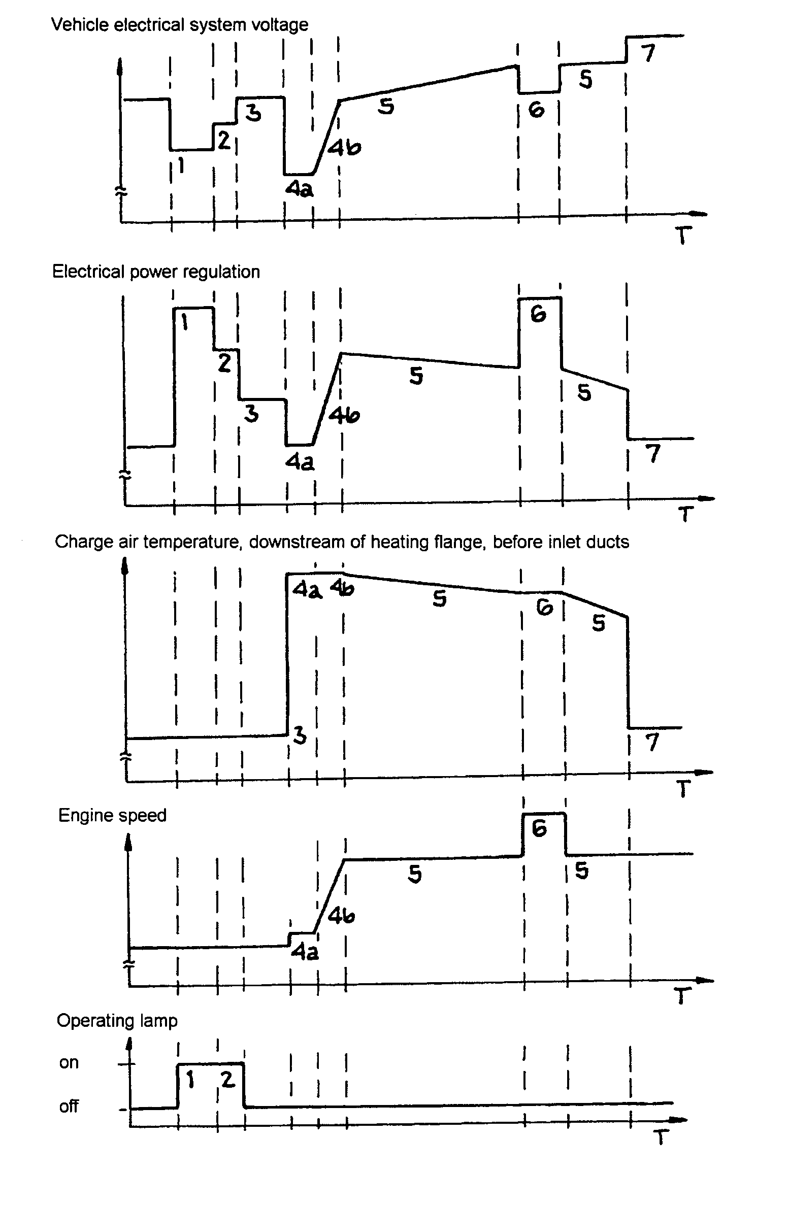
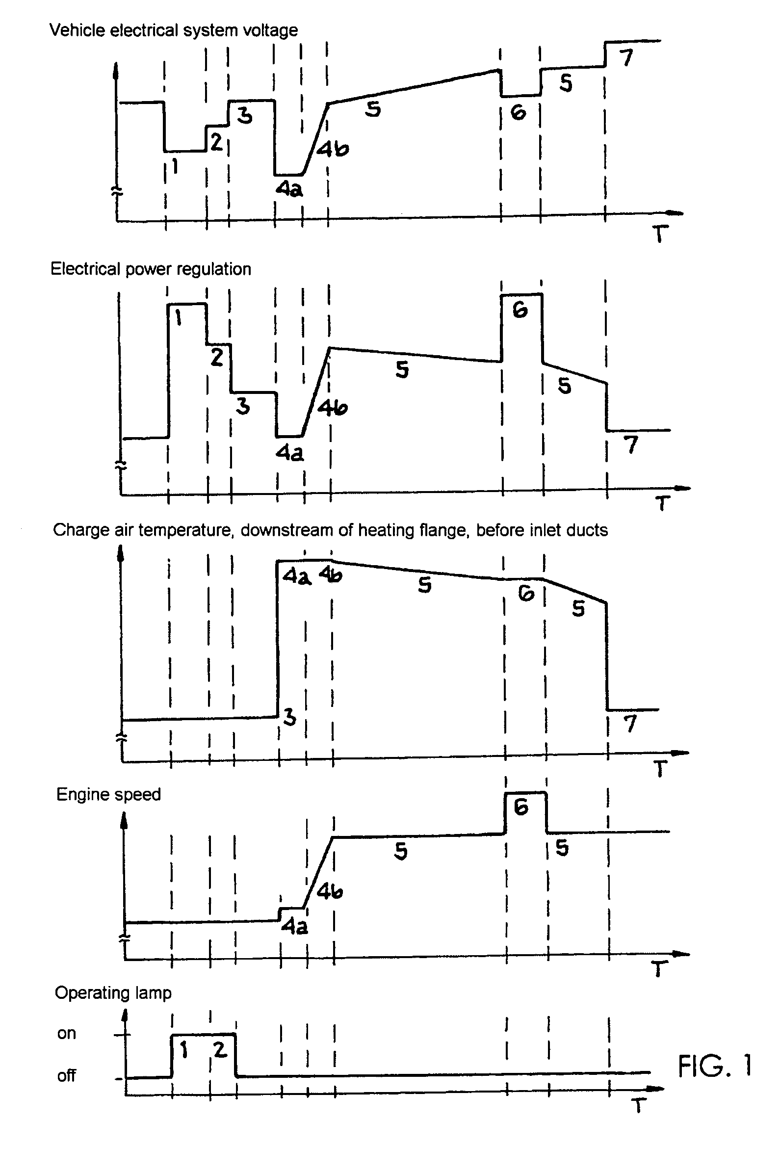
[0025]During the preglow phase 1, 2, 3 between switching on the ignition and activation of the starter, the current supplied to the heating elements in the heating flange is variably controlled. During a first time period 1, the heating element is initially supplied with full current until the heating flange reaches a reference temperature. After the reference temperature has been reached, a post-heating phase 2 and a start-readiness phase 3 begin in which the heating power is controlled in such a way that the heating flange is kept at a constant temperature. The profile of the vehicle electrical system voltage shows a sharp drop during the supply of full current 1 but recovers markedly during the post-heating phase 2 and the start-readiness phase 3. During the preglow phase, no charge air is yet taken in and the engine is not yet turning. The start-up phase begins when the starter of the internal combustion engine is activated. In a first time period 4a of the start-up phase, the s...


PUM


Abstract

In a method for heating up the intake air of an internal combustion engine during the preglow phase or start-up phase, the heating power is controlled by a control unit of the engine electronics as a function of the operating data of the internal combustion engine. During the preglow phase, the heating element is initially supplied with full current until the heating element reaches its reference temperature. After the reference temperature has been reached and until the start-up phase, a post-heating phase begins in which the heating element is kept at a constant temperature by way of a relatively low power. During the start-up phase, in a first time period, the heating element is switched off, and in a second time period in which the speed of the internal combustion engine is raised to the starting speed, the heating element is switched on again.

Description

BACKGROUND AND SUMMARY OF THE INVENTION[0001]This invention relates to a method for heating up the intake air, in particular for an internal combustion engine in the start-up or warm-up-phase.[0002]Heating up the intake air in internal combustion engines, in particular in diesel engines in the start-up and warm-up phases, is necessary for several reasons. At low ambient air temperatures and consequently at low intake air temperatures, an insufficient post-compression temperature and hence an increasing ignition delay occur, in diesel engines in particular, so that the period between the fuel entering the combustion space and igniting becomes too long. In addition, local over-enrichment, incomplete combustion and high pressure gradients occur at low intake temperatures as a result of sudden mixture conversion in the cylinder. The results are greatly increased hydrocarbon emissions in the exhaust gas, knocking of the diesel engine and the disadvantages resulting from this such as seve...

Claims


Application Information

Patent Timeline
Patent Type & Authority Patents(United States)
IPC IPC(8): F02N17/04F02N19/04F02D9/10F02M31/13F02M31/135
CPCF02D9/10F02M31/13F02M31/135Y02T10/126Y02T10/12
Inventor JOPPIG, PETERLANTERMANN, FRANKSCHMID, FRIEDRICHVOGEL, KARL-HEINZ
Owner DAIMLER AG
Why Eureka
Try Eureka