Quantum computer apparatus

a technology of quantum computers and apparatuses, applied in the field of quantum computers, can solve the problems of little extensibility in the number of quantum bits, and no practical methods for overcoming these disadvantages are known so far

Inactive Publication Date: 2008-12-16
KK TOSHIBA
View PDF3 Cites 14 Cited by
  • Summary
  • Abstract
  • Description
  • Claims
  • Application Information

AI Technical Summary

Problems solved by technology

Thus, the conventional quantum computers are disadvantageous in that it is necessary to read a single quantum, i.e., to detect a faint signal when a computation result is read, or there is little extensibility in the number of quantum bits.
No practical methods for overcoming these disadvantages are known so far.

Method used


Image

  • Quantum computer apparatus
  • Quantum computer apparatus
  • Quantum computer apparatus

Examples


embodiment 1

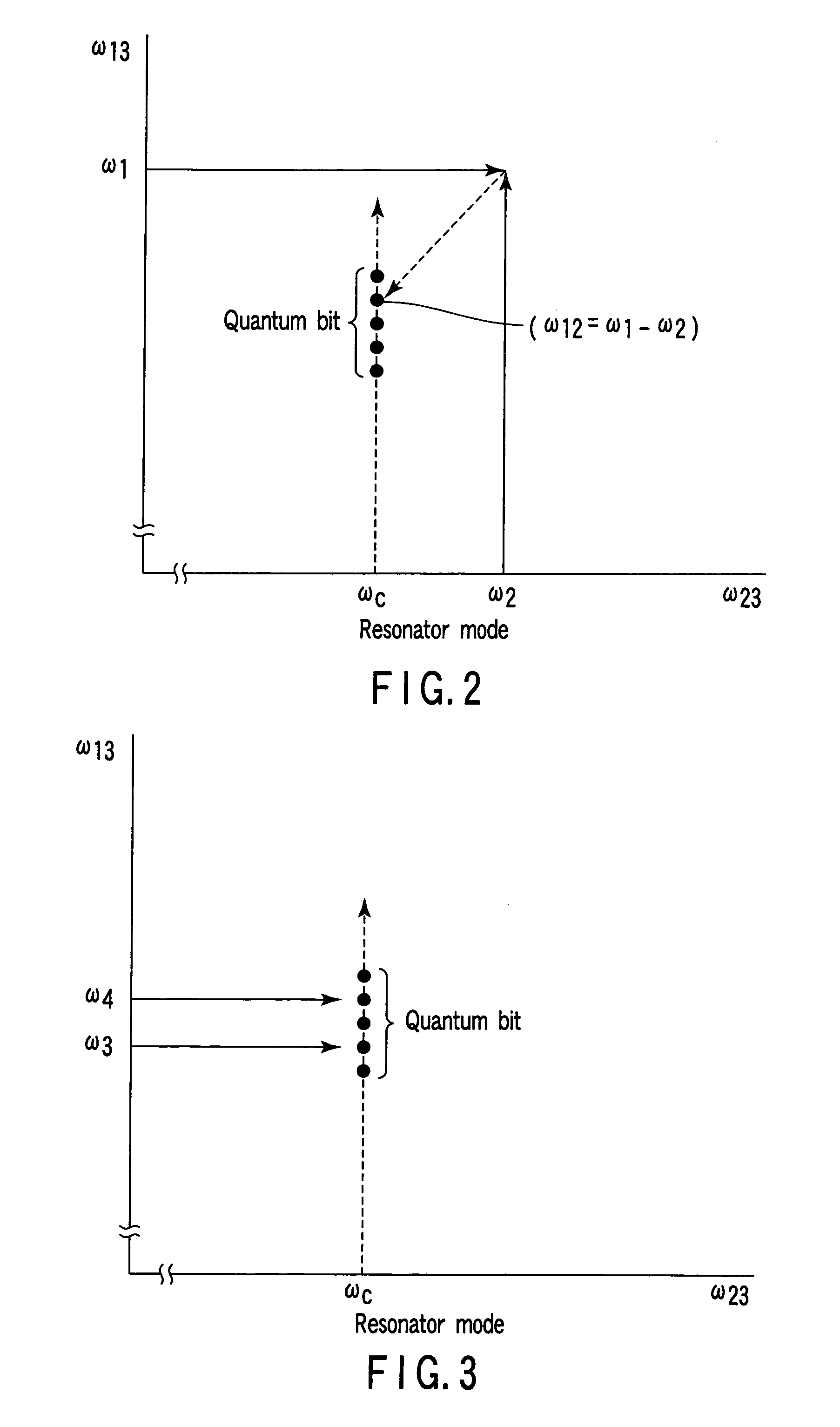
[0041]Referring to FIG. 7, a quantum computer according to a first embodiment will be described. In this embodiment, Pr3+ ions contained in Pr3+:Y2SiO5 crystal, in which 0.01% Y+3 ions are replaced with Pr3+ ions, are utilized as physical system groups (quantum bit groups) forming a plurality of quantum computer elements that simultaneously operate. FIG. 7 shows the positions on the transition frequency plane of Pr3+ ions used as quantum bits in the quantum computer of the embodiment.

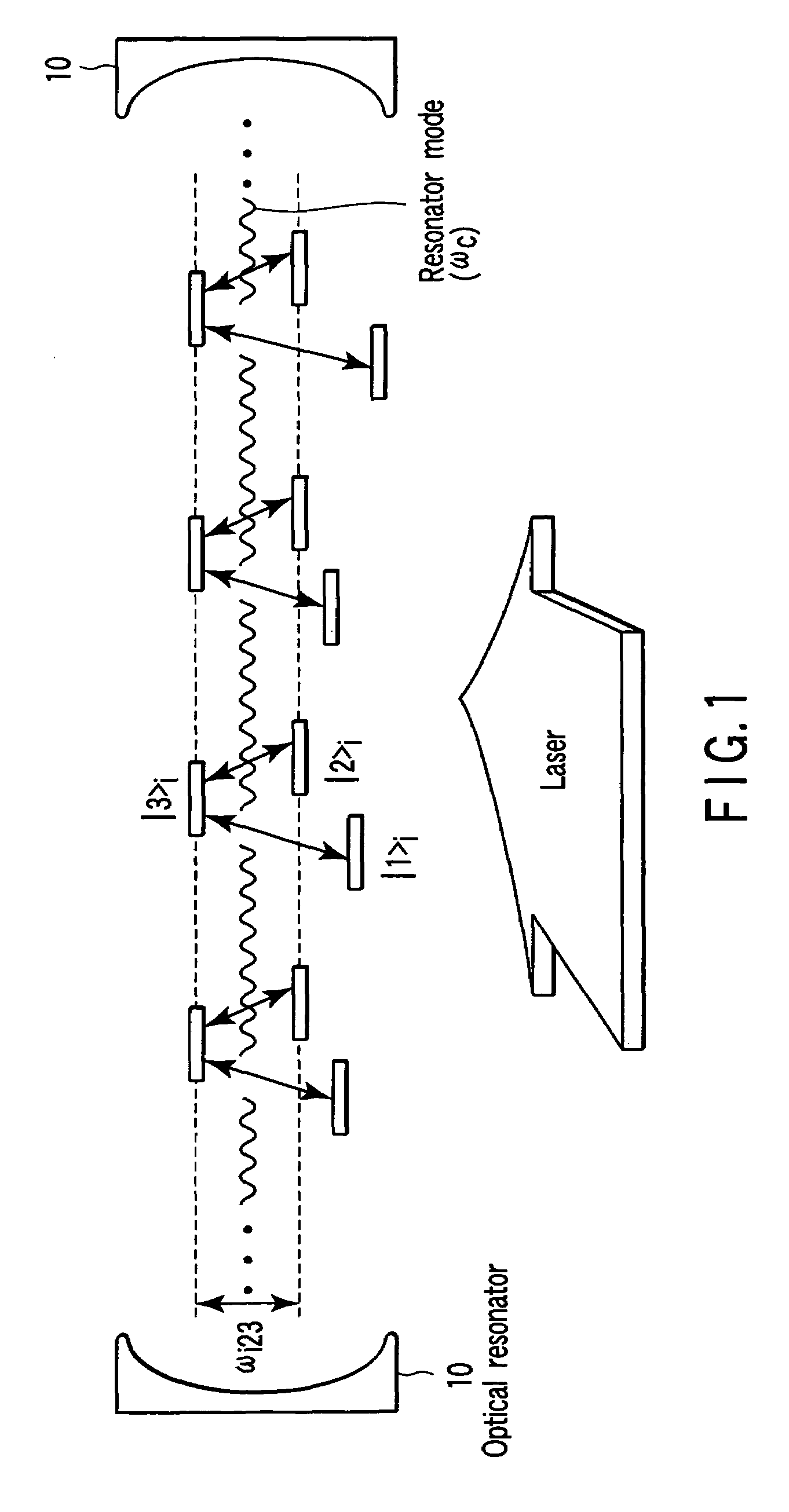
[0042]Opposite two surfaces of the Pr3+:Y2SiO5 crystal are polished, thereby forming a dielectric multi-layer mirror having a reflectance of 99.99% or more near 606 nm. Thus, an optical resonator with a free spectral range (FSR) of about 7.8 GHz is formed. This crystal is placed in a cryostat with an optical window, and is kept at the liquid helium temperature. This optical resonator has three resonator modes near 16501.12 cm−1, 16501.35 cm−1 and 16501.58 cm−1. Assume that these resonator modes are mode...

embodiment 2

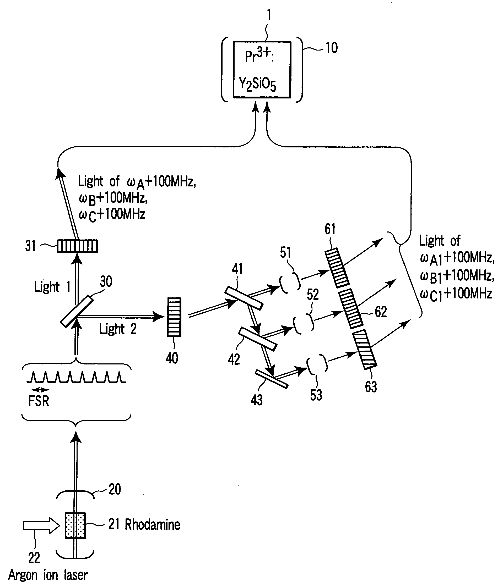
[0047]Referring to FIG. 8, a quantum computer according to a second embodiment will be described. In the second embodiment, a dye (rhodamine) 21 is made to flow in an optical resonator 20 having the same FSR as the optical resonator 10 (see the first embodiment) formed using opposite two surfaces of Pr3+:Y2SiO5 crystal 1, and is excited by an argon ion laser 22 to perform multi-mode oscillation. This is used instead of the three ring dye lasers employed in the first embodiment. The other structures are similar to those of the first embodiment, and quantum bit operations are performed in the same manner as in the first embodiment.

[0048]Resulting from the multi-mode oscillation, a laser that oscillates in units of 9.8 GHz is acquired. The beam emitted from this laser is split into two components by a splitter 30. One of the split components, which will be referred to as “light 1”, is passed through an acoustooptical effect element 31, where it is subjected to frequency shifting. As a ...

embodiment 3

[0049]In a third embodiment, the Pr3+:Y2SiO5 crystal employed in the first embodiment is kept at 1.4 K. The resonator formed of this crystal is made to have an FSR of 100 kHz.

[0050]In the same manner as in the first embodiment, photon ejection is arranged to be detectable regardless of whether it is performed in one or another of the three resonator modes (assumed to be resonator mode D (with an angular frequency ωD), resonator mode E and resonator mode F) separate from each other by FSR that causes interaction of quantum bits when detecting ions usable as the quantum bits. In this state, sweeping of a narrowed laser beam is performed within a range of approx. 200 kHz around an angular frequency higher than ωD by 2×17.3 MHz, thereby detecting a light beam of a particular angular frequency that causes three photons to be ejected in the respective three modes. Thus, three physical systems are detected, which have respective angular frequencies corresponding to transitions that are not...


PUM

PropertyMeasurementUnit
reflectanceaaaaaaaaaa
frequencyaaaaaaaaaa
transition angular frequencyaaaaaaaaaa

Abstract

Quantum computer includes optical resonator including system group containing systems each having energy states highest-energy state |3>, and other two energy states |1> and |2>, fourth or more states |p>, transition angular frequency (ωij) between |i> and |j>, homogeneous broadening (Δωhomo,ij) in transition angular frequency between |i> and |j>, optical resonator having resonator modes, ωck of kth resonator mode, and emitting unit configured to emit light beam to system group, and wherein |ωcl−ωcm|>Δωhomo,23, system group includes system subgroups Aq having respective ω23 which resonate with respective ωcq of resonator modes, and emitting unit is arranged to apply light beam of two wavelengths and other light beam to s(1)th quantum bit Aqs(1) (s(1)1˜r) formed of r systems selected from each Aq, light beam of two wavelengths simultaneously causing two-photon resonance on Aq at ω12 or ω1p, other light beam simultaneously causing one-photon resonance on Aq at ω13 or ωp3.

Description

CROSS-REFERENCE TO RELATED APPLICATIONS[0001]This application is based upon and claims the benefit of priority from prior Japanese Patent Application No. 2004-250513, filed Aug. 30, 2004, the entire contents of which are incorporated herein by reference.BACKGROUND OF THE INVENTION[0002]1. Field of the Invention[0003]The present invention relates to a quantum computer formed of a plurality of independent quantum computer elements operating parallel to each other, from which the computation results of the elements can be acquired as a strong signal representing them.[0004]2. Description of the Related Art[0005]In quantum computers utilizing a single quantum, such as an atom or ion, when a computation result is read, a quantum state of, for example, a single atom must be read, which means that an extremely faint signal must be detected. NMR quantum computers are exceptional. Since in these computers, individual molecules in a solution serve as independent quantum computers, when comput...

Claims


Application Information

Patent Timeline
Patent Type & Authority Patents(United States)
IPC IPC(8): H01S3/00G02F3/00
CPCB82Y10/00G06N99/002G06N10/00
Inventor ICHIMURA, KOUICHIGOTO, HAYATOSHIOKAWA, NORITSUGU
Owner KK TOSHIBA
Why Eureka
Try Eureka