Thin plate drilling and milling machine

a thin plate and milling machine technology, applied in the direction of portable drilling machines, drilling/boring measurement devices, manufacturing tools, etc., can solve the problems of annoying some conventional machine tools, not only laborious but often inaccurate, and thin plate may not have the structural integrity to remain completely flat, etc., to prevent abrasion to the underside and easy over the machine tool bed

Inactive Publication Date: 2008-12-23
LEE S PETER +1
View PDF15 Cites 43 Cited by
  • Summary
  • Abstract
  • Description
  • Claims
  • Application Information

AI Technical Summary

Benefits of technology

[0013]Therefore, an important object of the invention is to maintain a workpiece at a constant distance from the bottom of the workpiece to the bed of the drilling and milling machine regardless of the thickness of the workpiece to permit support from beneath. This object is accomplished by utilizing a pair of opposed workpiece holding bars, with each bar having longitudinal notches configured to hold the edges of a workpiece in a horizontal position. The longitudinal notch within each opposed bar has a horizontal bottom surface configured to interface with a bottom portion of the thin plate workpiece, and a sloped top angle surface configured to interface with a top edge of various thickness of the thin plate workpiece, thereby being capable of accommodating a wide variety of workpieces while always maintaining the proper bottom distance.
[0014]The third problem of a workpiece bowing under machining pressure is partially answere...

Problems solved by technology

There are some annoying problems with some conventional machine tools, in particular with a CNC drilling and milling machine.
First, in a normal drilling or milling process, the operator is required to align the drill or milling bit at an exact location or reference point before the work can proceed.
It is also not only labor intensive but often inaccurate un...

Method used


Image

  • Thin plate drilling and milling machine
  • Thin plate drilling and milling machine
  • Thin plate drilling and milling machine

Examples


Embodiment Construction

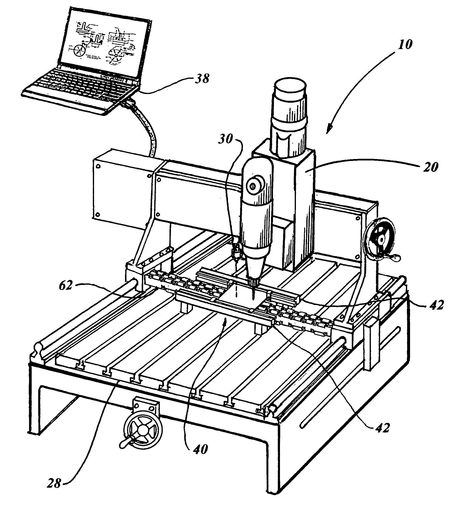
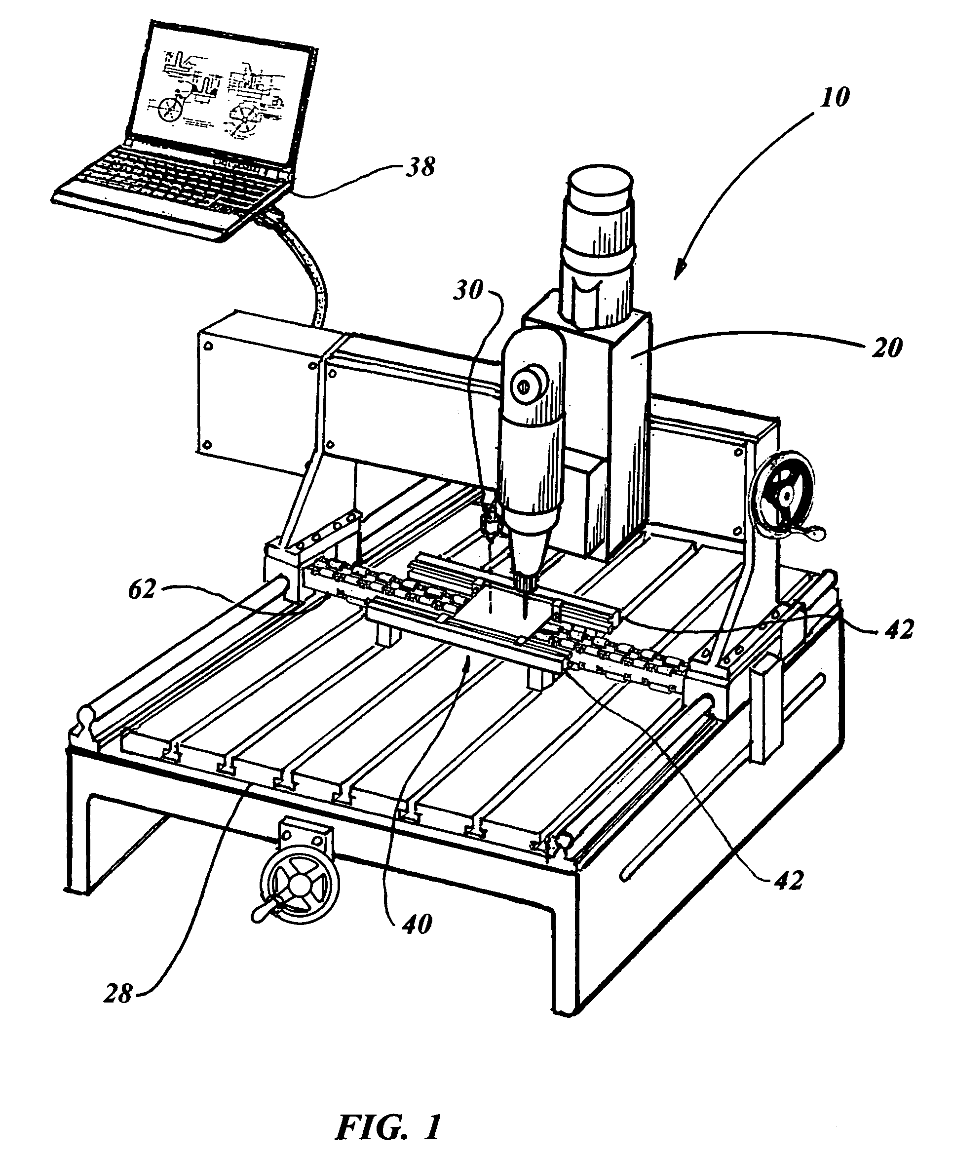
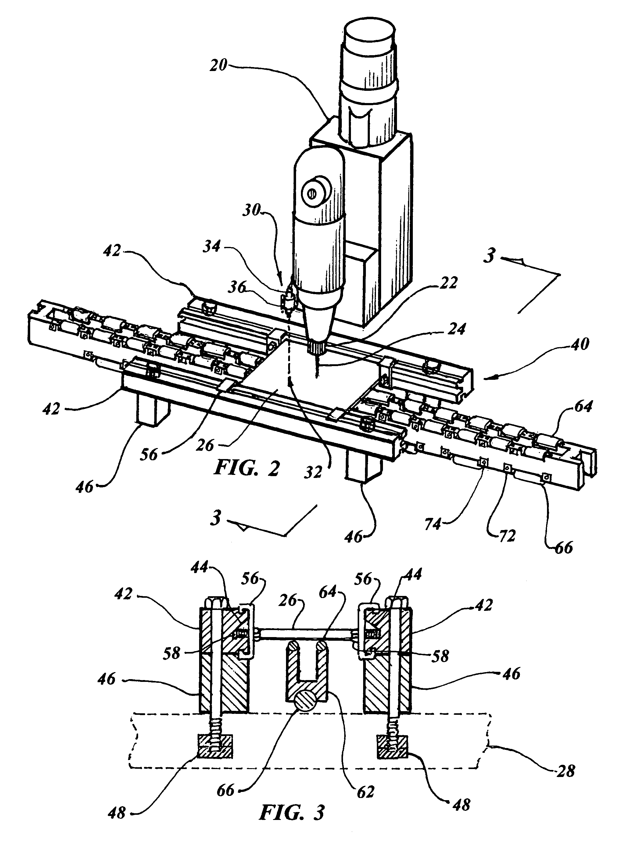
[0029]The best mode for carrying out the invention is presented in terms of a preferred embodiment for a thin plate drilling and milling machine 10. The preferred embodiment, as shown in FIGS. 1 through 13, is comprised of a movable drill motor platform 20 having a rotating spindle 22 that holds a drill bit 24 for drilling or a milling bit for milling into a thin plate workpiece 26, as illustrated in FIG. 2. It should be noted that the milling bit is not illustrated as its configuration varies considerably according to the type of machining required and the bit is well known in the art and has been in use for well over a century. The movable drill motor platform 20 travels in the X and Y axis relative to a T-groove base 28 of the drilling and milling machine 10, with the rotating spindle 22 moving up and down in the Z axis.

[0030]A laser reference point finder 30 provides a laser beam that is displayed on the workpiece 26 to visually indicate a CNC reference point 32. The reference p...


PUM

PropertyMeasurementUnit
Volumeaaaaaaaaaa
Thicknessaaaaaaaaaa
Electric potential / voltageaaaaaaaaaa

Abstract

A CNC drilling and milling machine comprised of a movable drill motor platform (20) with a laser reference point finder (30) in the form of a laser (34) that is attached to the machine adjacent a spindle (22). The reference point is aligned on the workpiece (26) with an identical reference located in a CNC computer (38). A workpiece holder (20) has two opposed bars (42) attached to a T-groove base of the drilling and milling machine, with each bar having a longitudinal notch (44) for holding the edges of a workpiece (26). A plate compression support and debris collecting member (62) collects debris and provides support for the workpiece (26). The entire platform is moved to drill or mill at predetermined computer selected positions, having the initial reference point (32) located with the calibrated laser beam.

Description

TECHNICAL FIELD[0001]The invention generally pertains to drilling and milling machines, and more specifically to a Computer Numerical Control (CNC) machine having a reference point finder to locate an exact position on a workpiece, a thin plate workpiece holder and a compression support and debris collector for the workpiece.BACKGROUND ART[0002]Previously, many types of holding and centering devices have been used to provide an effective means for holding a workpiece in a machine tool such as a milling or drilling machine.[0003]The prior art listed below did not disclose patents that possess any of the novelty of the instant invention; however the following U.S. patents are considered related:[0004]U.S. Pat. No.InventorIssue Date5,375,952LineDec. 27, 19946,679,659Lasch et al.Jan. 20, 20046,733,217 B2Schworer et al.May 11, 20046,745,455 B2Popp et al.Jun. 8, 20046,832,878 B2Elrod et al.Dec. 21, 2004[0005]Line in U.S. Pat. No. 5,375,952 teaches a vertical milling and boring machine inc...

Claims


Application Information

Patent Timeline
IPC IPC(8): B23B39/00
CPCB23B39/06B23B39/08B23B2260/092Y10T408/563Y10T408/561Y10T409/309576Y10T408/50Y10T29/5107Y10T408/21
Inventor LEE, S. PETERPAN, FRANCIS
Owner LEE S PETER
Why Eureka
Try Eureka