Fluid dispenser assembly

a dispenser and assembly technology, applied in the field of fluid dispensers, can solve the problems of affecting the quality of the product, and difficult assembly, and achieve the effects of convenient compatibility, low manufacturing cost, and low manufacturing cos

Active Publication Date: 2008-12-23
LUCAS PUBLICATIONS
View PDF58 Cites 26 Cited by
  • Summary
  • Abstract
  • Description
  • Claims
  • Application Information

AI Technical Summary

Benefits of technology

[0012]The present invention is designed to overcome the shortcomings associated with the disclosure of Abbas and other known fluid dispensers by providing a dispenser assembly that is cheaper to manufacture, requires few parts to assemble, and is readily compatible with standard high speed filling machines. As discussed more fully herein, the present invention requires few parts; namely, an end cap, a fluid insert containing fluid materials, and an outer casing. Unlike the prior art disclosures, each of these parts can be assembled together without the use of additional parts, such as adhesives or retaining rings, or steps such as screwing the different components together. The present invention further permits a manufacturer to sell a dispenser assembly to cosmetic companies and the like seeking to dispense their products (such as lotions, gels, etc.) into dispensers using a high speed filling process. The present invention is fully compatible with standard high speed filling apparatuses. The dispenser assembly can be provided to cosmetic companies and the like in an almost completely assembled manner and placed directly onto standard high speed filling apparatuses. The only assembly required after filling is the addition of a seal cap to seal the dispenser once the cartridge of the dispenser has been filled with the desired fluid material. In accordance with another important feature of the present invention, the capping process can also take place as part of the high speed filling process, further cutting down on the assembly time. The steps required to assemble the fluid dispenser greatly differs from known dispensers, which require the separate steps of filling the cartridge, sealing the cartridge, and then assembling the cartridge into the holder. The few steps required to assemble and fill the dispenser assembly according to the present invention increases production, while minimizing overall costs. Accordingly, various dispenser assemblies in accordance with the present invention are disclosed which achieves each of these shortcomings.
[0018]In accordance with another aspect of the present invention, there is provided a dispenser assembly for dispensing a predetermined amount of fluid material comprising a fluid insert and an outer casing. The fluid insert has a body including a first end and a second end, a hollow chamber for storing a fluid material, a seal cap mounted to the first end for sealing the fluid insert, a pump connected to the second end for dispensing a predetermined amount of fluid material, a notch on the body displaced from the second end, and a protruding ridge displaced from the first end. The outer casing has an interior chamber for receiving the fluid insert and a first end and a second end. The applicator is arranged at the first end for applying the fluid material dispensed from the pump of the fluid insert to a surface. There is at least one tab arranged within the interior chamber of the outer casing and it is constructed and arranged to fit within the notch so as to guide movement of the fluid insert within the outer casing. The outer casing also has a ridge arranged within the interior chamber of the outer casing that is operative to restrict removal of the fluid insert when the fluid insert is assembled within the interior chamber.

Problems solved by technology

Some of the pieces, such as a separate applicator tip, are relatively small in size and can prove difficult to assemble.
The configuration of known dispensers therefore requires extraneous parts and steps to complete the dispenser assembly process, which, in turn, drives up the costs for the manufacturer.
These drawbacks are further compounded by the problems associated with filling known dispensers with fluid materials.
There are many problems, however, associated with the purchase and subsequent filling of known dispensers by a purchasing company.
It is not cost-effective to fill known dispensers with fluid product using standard high-speed filling apparatuses and processes.
Such dispensers often vary in shape and size and are not readily adaptable to preexisting high speed filling machines utilized by a particular company.
For example, the shape of the dispenser body may not be compatible with the parts of the preexisting filling machine used to hold the dispenser during the filling process, or the opening of the cartridge may not be large enough (or even too small) to receive the nozzle of the filling apparatus that dispenses the fluid material from the filling apparatus to the cartridge.
In some situations, it is too costly to adapt a preexisting filling machine to fit a particular dispenser, which results in the inability to use such a dispenser in a high speed filling process, or similar type of filling process.
This often forces the cosmetic company to either select an alternative dispenser, or to use an alternative slower process.
Each of these problems is a costly venture for a purchasing company, who then passes the additional cost on to the consumer.
There are also additional costs associated with assembling the dispenser once the dispenser has been filled with the desired fluid material.
This task proves to be especially cumbersome when the dispenser has several components that need to be assembled after the filling process is completed.
The added steps and time needed to assemble and fill such dispensers, slows down the filling process and drives up the filling costs.
It also compromises the quality and integrity of the fluid material sitting in the dispenser because it leaves the fluid materials subject to contamination by dust, air, etc., until the dispenser is sealed.
Despite the seemingly relative simplicity of these embodiments, there are still costly drawbacks associated with the manufacture of the Abbas dispensers, and the subsequent filling of the Abbas dispensers with fluid materials.
This design is believed to prevent the pre-assembly of the cartridge into the holder when the cartridge is provided to a filling manufacturer because pre-assembly might cause premature puncturing of the cartridge.
Moreover, the design of the cartridge typically requires additional screwing or the use of adhesives or the like to secure the cartridge within the holder.

Method used


Image

  • Fluid dispenser assembly
  • Fluid dispenser assembly
  • Fluid dispenser assembly

Examples


Embodiment Construction

[0044]In describing the preferred embodiments of the subject matter illustrated and to be described with respect to the drawings, specific terminology will be resorted to for the sake of clarity. However, the invention is not intended to be limited to the specific terms so selected and it is to be understood that each specific term includes all technical equivalents which operate in a similar manner to accomplish a similar purpose.

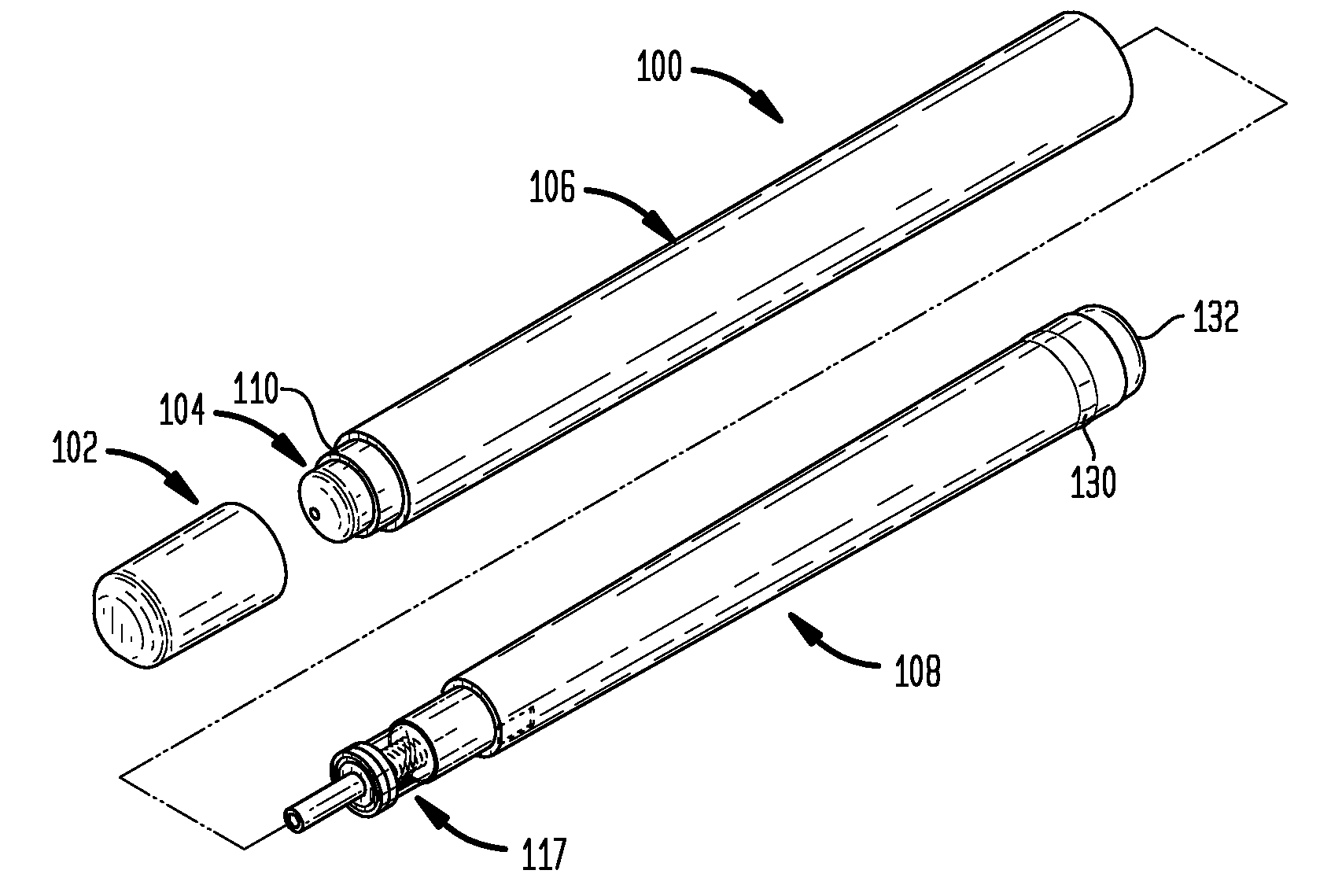
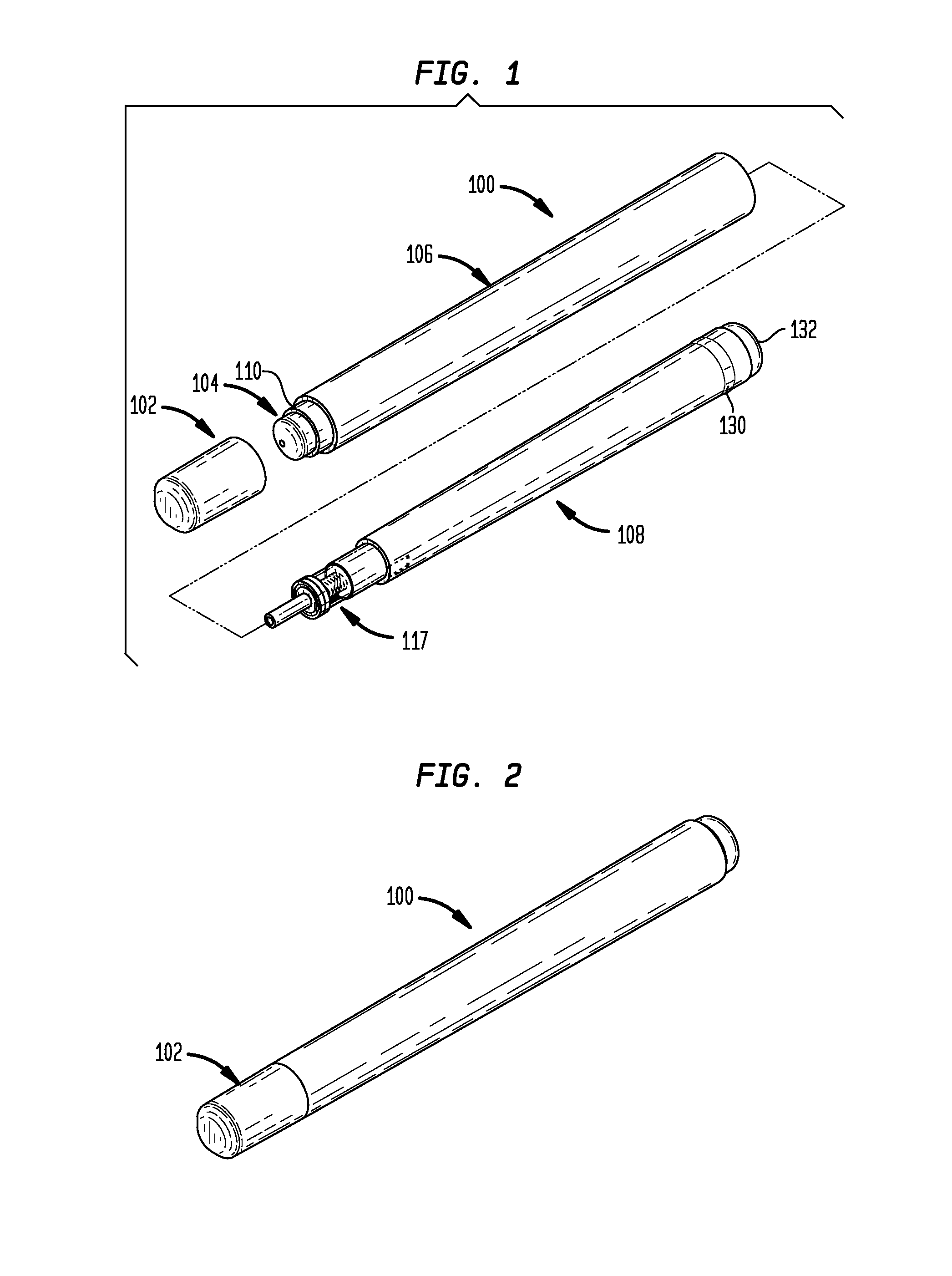
[0045]The present invention is generally directed to a dispenser assembly 100 shown in FIG. 1 for dispensing predetermined amounts of fluid materials. The material, such as lotion, is stored within a fluid insert 108 and dispensed therefrom in response to pressure applied by a user onto the fluid insert 108, which, in turn, actuates the pump 117. The dispenser also contains an outer casing 106 that holds the fluid insert 108.

[0046]It is to be understood that the dispenser for fluid materials of the present invention may be utilized to dispense various liqu...


PUM


Abstract

The present invention is directed toward a cost effective instrument for storing a fluid material, and applying a predetermined amount of the fluid material to a surface. The instrument is comprised of few parts including an outer casing and a fluid insert, making the instrument cheaper to manufacture, and easy to assemble. The embodiments disclosed can be provided in a pre-assembled form to cosmetic companies and the like seeking to fill a dispenser with their fluid cosmetic products. The ability to provide dispensers in a pre-assembled form, combined with the compatibility of the fluid dispensers with industrial high speed filling machines, reduces the overall filling costs to the cosmetic company, as well as the cost to the consumer.

Description

CROSS-REFERENCE TO RELATED APPLICATIONS[0001]The present application is a continuation-in-part of U.S. patent application Ser. No. 29 / 196,339, filed on Dec. 24, 2003, the disclosure of which is incorporated herein by reference.BACKGROUND OF THE INVENTION[0002]The present invention relates generally to a fluid dispenser, and more particularly to a cost-effective dispenser assembly that is fully compatible with high-speed in-line filling apparatuses, capable of dispensing predetermined amounts of fluid materials, and has few components to assemble.[0003]Various types of dispensers for fluids are well known in the art. Dispenser's typically comprise a cartridge for holding the fluid material, as well as a spray, pump, or plunger to dispense the fluid material out of the cartridge. Some dispensers have a spray pump attached to a pump line that runs through a cartridge containing fluid material, such as perfume. When the user depresses the spray pump, fluid material flows through the lin...

Claims


Application Information

Patent Timeline
Patent Type & Authority Patents(United States)
IPC IPC(8): B65D88/54A46B11/04B65D47/10B05C17/005B65D83/76B67D7/06B67D7/08B67D7/38B67D7/60E21B17/10G01F11/06G01F11/30G01F11/36G01F11/42
CPCG01F11/025
Inventor FRANCAVILLA, FRANKKEARSEY, KEVIN F.X.
Owner LUCAS PUBLICATIONS
Why Eureka
Try Eureka