Dynamic match low noise amplifier with reduced current consumption in low gain mode

a low-noise amplifier and low-gain technology, applied in the field of low-noise amplifiers, to achieve the effect of reducing the gain of the lna and reducing the average current consumption of the lna

Active Publication Date: 2009-01-06
QORVO US INC
View PDF4 Cites 48 Cited by
  • Summary
  • Abstract
  • Description
  • Claims
  • Application Information

AI Technical Summary

Benefits of technology

[0010]In one embodiment, the present invention is implemented using two parallel cascode transistor circuits and one center-tapped source inductor to create a single-ended LNA. During the normal mode of operation, both cascode circuits are active to provide sufficient gain to amplify small RF signals. During the low-gain mode of operation, one of the cascode circuits is powered down. This reduces the gain of the LNA, and reduces the average current consumption of the LNA. The LNA input impedance remains close to the matching point between normal mode and low-gain mode by the addition of an inductor between the common source or emitter elements of the two cascode circuits. The addition of the inductor compensates for the impedance change by the gate capacitance of the off-transistor at the input node. The phase of the RF output signal changes little by switching between normal and low-gain modes.

Problems solved by technology

One design challenge occurs when an LNA is designed with sufficient RF gain to amplify the smallest signals, such as signals at −100 dbm.

Method used


Image

  • Dynamic match low noise amplifier with reduced current consumption in low gain mode
  • Dynamic match low noise amplifier with reduced current consumption in low gain mode
  • Dynamic match low noise amplifier with reduced current consumption in low gain mode

Examples


Embodiment Construction

[0021]The embodiments set forth below represent the necessary information to enable those skilled in the art to practice the invention and illustrate the best mode of practicing the invention. Upon reading the following description in light of the accompanying drawing figures, those skilled in the art will understand the concepts of the invention and will recognize applications of these concepts not particularly addressed herein. It should be understood that these concepts and applications fall within the scope of the disclosure and the accompanying claims.

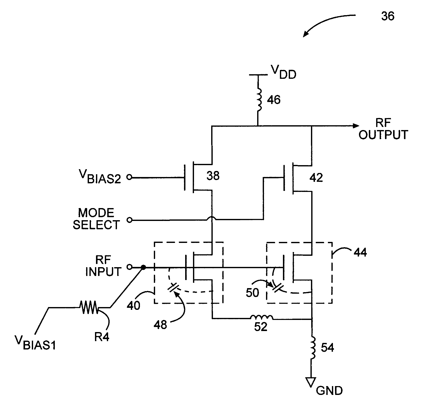
[0022]One embodiment of the present invention is a dual mode single-ended cascode LNA 36 using N-MOSFETs as the active elements as shown in FIG. 3. A main cascode transistor 38 and main gain transistor 40 form the main cascode circuit, while a normal mode cascode transistor 42 and normal mode gain transistor 44 form the normal mode cascode circuit with high gain. A common load inductor 46 is connected to both cascode circuits.

[002...


PUM


Abstract

The present invention is a dual mode LNA that can operate in either normal mode or low-gain mode, which has been designed to maintain a constant input impedance when switching between the two modes of operation. Maintaining constant input impedance is called a dynamic match. The LNA has been designed to maintain a constant bandwidth when switching between normal and low-gain modes of operation. Also, the LNA has been designed to consume much less average current when operating in the low-gain mode.

Description

[0001]This application claims the benefit of U.S. provisional patent application Ser. No. 60 / 790,720, filed Apr. 10, 2006, which is incorporated herein by reference in its entirety.FIELD OF THE INVENTION[0002]The present invention relates to Low Noise Amplifiers (LNAs) and mixers used in Radio Frequency (RF) communications circuitry, which is used in communications systems.BACKGROUND OF THE INVENTION[0003]LNAs are commonly used in RF circuits when small RF signals need to be amplified for further processing. A typical application is in the front end of an RF receiver. An LNA may be the first active component in the receiver's signal path. In many applications, RF receivers must be able to function over a wide dynamic range of received signals; therefore, an LNA in the front end of such an RF receiver must be able to function over a wide dynamic range. An operating range between −100 dbm to −25 dbm is not unusual.[0004]One design challenge occurs when an LNA is designed with sufficie...

Claims


Application Information

Patent Timeline
Patent Type & Authority Patents(United States)
IPC IPC(8): H03F3/04
CPCH03F1/0205H03F1/223H03F1/26H03F1/56H03F3/45188H03F3/72H03G1/0029H03G1/0088H03F2200/222H03F2200/294H03F2200/366H03F2200/492H03F2203/45386H03F2203/7236
Inventor YIM, SEONG-MOYAN, KELVIN KAI TUAN
Owner QORVO US INC
Why Eureka
Try Eureka