Single substrate electromagnetic actuator

a single-substrat actuator and actuator technology, applied in the field of single-substrat actuators, can solve the problems of not yet commercialization of the mems micro-valve, the current state of research in the field of micro-valves is not well established, and the mems valves developed in the research lab are simply not reliable and robust enough for commercial applications, etc., to achieve the effect of small dead volume, low power consumption system and low cos

Inactive Publication Date: 2009-01-06
AIR FORCE THE US SEC THE +1
View PDF20 Cites 41 Cited by
  • Summary
  • Abstract
  • Description
  • Claims
  • Application Information

AI Technical Summary

Benefits of technology

[0069]The electromagnetic force generator can include a coil or coils through which a current is provided, to generate the force, and / or a magnet. Further, the stability of the present membrane to remain in the first and / or second position can be provided without an induced force through the coil(s), making the design a low power consuming design.
[0109]Another object of the present invention includes providing a valve design that can be easily integrated into arrays, for fluid control, and also with control electronic circuits.

Problems solved by technology

Even though millions of dollars have been spent in the research, there has not yet been commercialization of the MEMS microvalve, quite unlike the silicon pressure sensor that has been largely commercialized in many engineering applications, including automobile, fluidic device, and jet propulsion.
The fact is that the MEMS valves developed in the research lab are simply not yet reliable and robust enough for commercial application [8, 9, 10].
The current state of research in the microvalve field is not well established, nor oriented into a particular application.
Another challenge in bringing MEMS device to market is the need for CMOS compatibility.
This has made MEMS fabrication more difficult, as its maximum fabrication temperature should be less than 400° C.
Unlike pressure sensors that require only a silicon membrane as the main component, the microvalve essentially comprises three main parts: an actuator, a cantilever / membrane, and fluidic connections [10, 11, 12, 13], all of which increase the complexity of the design and fabrication of the microvalve.
The design can be quite complex.
It required a small, yet reliable, silicon valve with extremely low leak rates and long shelf lives.
Further, it must survive the perils of space travel, which include unstoppable radiation, monumental shock and vibration forces, as well as extreme variations in temperature.
However, one has to be very careful because a small displacement may limit the microvalve performance due to clogging.
This type of actuator requires a lot of power consumption and has a long response in valve closing / opening.
However, the membrane deflection is generally large to avoid clogging.
However the response time is very slow, with the fastest achieved being 16 minutes using a 70 um thick Hydrogel and a 60 um porous back plate.
[11]Using the optimization of the flow back-The heating to fluid may not be applicable to somepressure in closing the valve reduces theMEMS application.
This valve is not suitable forgiven to the heating element.
Fluidic connections for the microvalve also present a challenge in the design.
Even though the wafer bonding processes are simple, they are not desirable because it closes the opportunity for the microvalve hybrid integration with the electrical circuit on a single wafer.
The yield rate of the wafer bonding is generally low and reduces the fabrication efficiency.
To fabricate a complete set of microvalves fully by surface micro-machining is not easy.
The current microvalve art has not yet fully fabricated the whole structure of the valve by MEMS surface micro-machining technique.
Yet these attempts are not suitable with the spirit of MEMS as a batch fabrication.
Thus, this kind of microvalve design will find itself difficult for commercialization in wide industrial area.

Method used


Image

  • Single substrate electromagnetic actuator
  • Single substrate electromagnetic actuator
  • Single substrate electromagnetic actuator

Examples


Embodiment Construction

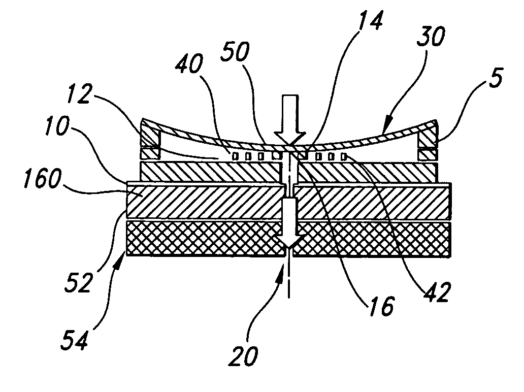
[0162]Referring now in detail to the figures, wherein like reference numerals represent like parts throughout the several views, the present actuating system 5 comprises a microvalve 10 incorporating a valve flow channel 20, a membrane / diaphragm 30, an membrane activating mechanism 40, and a latching system 50. The present actuator is an active device that involves the mechanical movement of a membrane by an electromagnetic driving force.

[0163]The geometry of the valve is basically built on a substrate 160 preferable Si wafer. The base of the valve 10 is made from NiFe alloy and a coil 42 built on top of the base. A circular post 15a with the height of 10-20 μm is built in order to have a membrane with dome 32 attached on the edge of the post 15a.

[0164]The base of the valve 10 is known as the seat 12, and interfaces with the rest of the micro-fluidic system. The membrane / diaphragm 30 deflects / actuates to close or open the fluid flow. The membrane activating mechanism 40 provides th...


PUM


Abstract

A microvalve which utilizes a low temperature (<300° C.) fabrication process on a single substrate. The valve uses buckling and an electromagnetic actuator to provide a relatively large closing force and lower power consumption. A buckling technique of the membrane is used to provide two stable positions for the membrane, and to reduce the power consumption and the overall size of the microvalve. The use of a permanent magnet is an alternative to the buckled membrane, or it can be used in combination with the buckled membrane, or two sets of micro-coils can be used in order to open and close the valve, providing the capability for the valve to operate under normally opened or normally closed conditions. Magnetic analysis using ANSYS 5.7 shows that the addition of Orthonol between the coils increases the electromagnetic force by more than 1.5 times. At a flow rate of 1 mL / m, the pressure drop is <100 Pa. The maximum pressure tested was 57 kPa and the time to open or close the valve in air is under 100 ms. This results in an estimated power consumption of 0.1 mW.

Description

BENEFIT CLAIMS TO PRIOR APPLICATIONS[0001]This application claims the benefit of U.S. Provisional Application No. 60 / 422,913, filed 1 Nov. 2002.GOVERMENT INTERESTS[0002]The present invention was made with government support by the US Air Force under Contract #F33615-01-1-2173, awarded by the Department of Defense (DARPA). The Government has certain rights in this invention.FIELD OF THE INVENTION[0003]The present invention is related to a single substrate actuator, and the fabrication of same. In particular, the present invention is related to a microfabricated magnetically actuated latching microvalve.BACKGROUND OF THE INVENTION[0004]MEMS technology has become increasing popular in the past decade. Many inventions for the manufacturing of high technology products have been made based upon the miniaturization using the MEMS technology.[0005]The microvalve is an important component in various fluidic applications, such as miniaturized chemical analysis systems, micro-pumps, and variou...

Claims


Application Information

Patent Timeline
Patent Type & Authority Patents(United States)
IPC IPC(8): H01H51/22F15C5/00F16K99/00
CPCF15C5/00F16K99/0001F16K99/0015F16K99/0046F16K2099/0069F16K2099/0074F16K2099/008F16K2099/0084F16K2099/0086B33Y80/00
Inventor BINTORO, JEMMY SUTANTOHESKETH, PETER J.
Owner AIR FORCE THE US SEC THE
Why Eureka
Try Eureka