Supercharge Your Innovation With Domain-Expert AI Agents!

Laser apparatus and production method of laser apparatus

a laser apparatus and production method technology, applied in lasers, semiconductor lasers, active medium materials, etc., can solve the problems of small amount of current that can be injected difficulty in large current injection into the active portion, so as to achieve easy production and large current

Inactive Publication Date: 2009-01-13
CANON KK
View PDF5 Cites 0 Cited by
  • Summary
  • Abstract
  • Description
  • Claims
  • Application Information

AI Technical Summary

Benefits of technology

The present invention provides a laser apparatus with a large amount of current injection and easy production. The apparatus includes a light-emitting region on a substrate, a periodic refractive index structure, and electrodes of a three dimensional photonic crystal material. The laser apparatus has high efficiency and can be produced using simple steps. The invention also provides a method for producing the laser apparatus. The technical effects of the invention include increased current injection, simplified production process, and improved efficiency of the laser apparatus.

Problems solved by technology

However, the prior art semiconductor laser device, disclosed In Japanese Patent Application Laid-Open No. 2001-257425, has the following problems.
The prior art semiconductor laser device has a problem such that, since there are formed on the photonic crystal structure electrodes composed of thin films of materials different from the material of the photonic crystal structure, it is difficult to inject a large amount of current into the active portion.
Therefore, there is a problem that the amount of current that can be injected into the active portion is small.

Method used


Image

  • Laser apparatus and production method of laser apparatus
  • Laser apparatus and production method of laser apparatus
  • Laser apparatus and production method of laser apparatus

Examples


first embodiment

[0073]First, a laser apparatus according to first Embodiment of the present invention will be described.

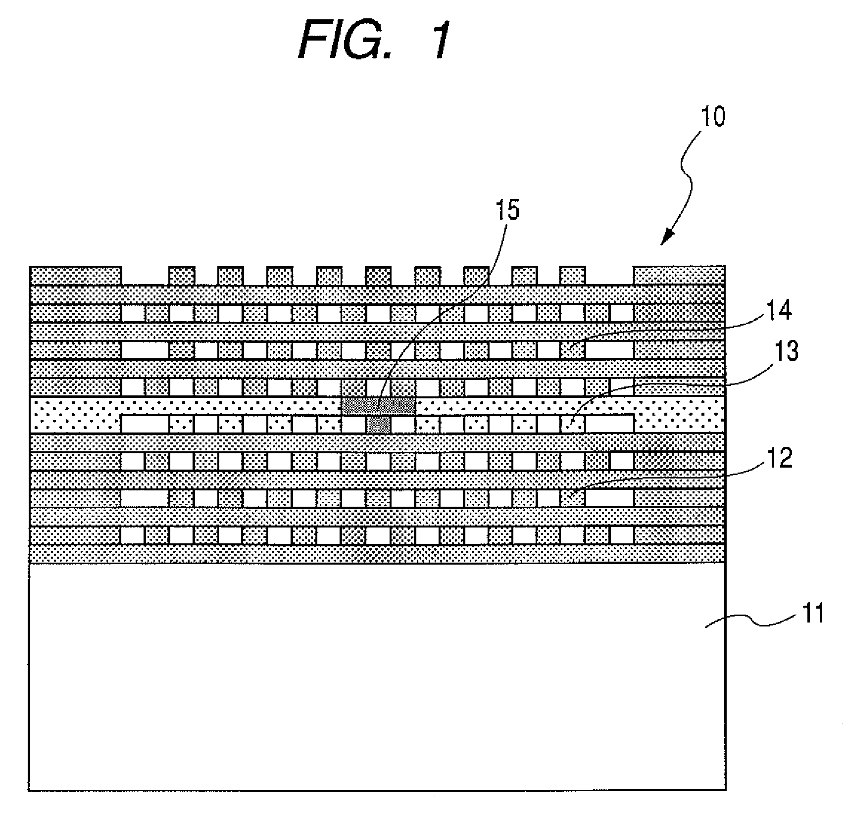
[0074]FIG. 1 is a schematic cross-sectional view illustrating a configuration of a laser apparatus according to this embodiment.

[0075]In FIG. 1, a laser apparatus 10, a substrate 11, an n-type three-dimensional photonic crystal 12, an i-type three-dimensional photonic crystal 13, a p-type three-dimensional photonic crystal 14, and an active portion 15, are illustrated.

[0076]The laser apparatus 10 according to this embodiment is composed of the n-type three-dimensional photonic crystal 12, the i-type three-dimensional photonic crystal 13, the p-type three dimensional photonic crystal 14 provided on the substrate 11, the active portion 15 inserted into the i-type three-dimensional photonic crystal 13, and a waveguide (not shown).

[0077]For example, the substrate 11 is formed of synthesized quartz, and the n-type, i-type, and p-type three-dimensional photonic crystals are formed of a ...

second embodiment

[0094]Next, a laser apparatus according to second Embodiment of the present invention will be described.

[0095]FIG. 3 is a schematic cross-sectional view illustrating the configuration of the laser apparatus of this embodiment.

[0096]In FIG. 3, a laser apparatus 30, a substrate 31, an i-type three-dimensional photonic crystal 32, and an active portion 33, are illustrated.

[0097]The laser apparatus according to this embodiment is constituted by forming the three dimensional photonic crystal 32 of i-type titanium oxide on the substrate made of, for example synthesized quartz, and inserting the active portion 33 in the center of the three dimensional photonic crystal 32 which exhibits a light emission action upon irradiation with light.

[0098]The i-type three dimensional photonic crystal 32 has, for example, a woodpile structure whose periodicity is about 250 nm, and the number of stack layers is, for example, 24.

[0099]An external exciting light is injected into the active portion 33 to ge...

third embodiment

[0106]Next, a production method of a laser apparatus according to third Embodiment of the present invention will be described. FIGS. 5A, 5B, 5C, 5D, 5E, 5F, 5G, 5H and 5I are schematic cross-sectional views illustrating the production method of the laser apparatus according to this embodiment.

[0107]Incidentally, like elements in the figure are denoted by like reference numerals. However, the material, structure, shape, and numeral values according to the present invention, are not limited to those herein described.

[0108]In FIGS. 5A, 5B, 5C, 5D, 5E, 5F, 5G, 5H and 5I, there are shown a substrate 51, an alignment mark 52, an active portion 60, a resist pattern 54, a secondary mask pattern 55, a sacrifice layer 56, a defect portion 57 of a photonic crystal, and a transparent material thin film 53.

[0109]In addition, a first portion of the three dimensional photonic crystal 70, a second portion of the three dimensional photonic crystal 80, and a third portion of the three dimensional pho...


PUM


Abstract

Provided are a laser apparatus into which a large current can be injected and a production method which enables easy production of the apparatus. A laser apparatus includes a light-emitting region on a substrate, and a periodic refractive index structure containing an i-type material provided at a periphery of the light-emitting region. Another laser apparatus includes a light-emitting region between a first electrode and a second electrode on a substrate, wherein at least one of the first and the second electrodes includes a periodic refractive index structure.

Description

BACKGROUND OF THE INVENTION[0001]1. Field of the Invention[0002]The present invention relates to a laser apparatus and a production method of a laser apparatus.[0003]2. Description of the Related Art[0004]In general, a semiconductor laser device includes a p-type electrode, an n-type electrode, a p-type optical waveguide, an n-type optical waveguide, and an active layer[0005]Being provided near the active layer and made of materials different from the material constituting the active layer, the electrodes and optical waveguides act as a resonator for confining the light generated in the active layer.[0006]By the above configuration, stimulated (or induced) emission of laser light is caused in the active layer, and the laser light is amplified in the resonator and then guided outside the device by the optical waveguides.[0007]Moreover, there is also a configuration using a Fabry-Perot resonator in which a cleavage plane is used as a resonator.[0008]However, since the above-mentioned ...

Claims


Application Information

Patent Timeline
Patent Type & Authority Patents(United States)
IPC IPC(8): H01S5/00H01S5/12
CPCH01S5/12H01S5/0425H01S5/105H01S5/183H01S5/04253H01S5/04256H01S5/04257H01S5/11
Inventor TAMAMORI, KENJIWANG, SHINAN
Owner CANON KK
Features
  • R&D
  • Intellectual Property
  • Life Sciences
  • Materials
  • Tech Scout
  • Unparalleled Data Quality
  • Higher Quality Content
  • 60% Fewer Hallucinations
Learn More