Hot magnetic separator process and apparatus

a technology of hot magnetic separator and process, applied in the direction of magnetic separation, solid separation, chemistry apparatus and processes, etc., can solve the problems of rare earth magnets corroding or rusting readily, the magnets themselves cannot survive the elevated temperatures, and the gap in the mineral processing industry

Active Publication Date: 2009-01-20
METSO OUTOTEC (FINLAND) OY
View PDF7 Cites 7 Cited by
  • Summary
  • Abstract
  • Description
  • Claims
  • Application Information

AI Technical Summary

Benefits of technology

[0029]In one aspect of the present invention there is provided a continuous process for separating particles according to their magnetic properties comprising the steps of: feeding a thin bed of hot particles including a plurality of factions of materials having different magnetic properties onto a moving surface spaced closely above a stationary magnetic assembly including a plurality of magnets producing a magnetic flux density capable of producing a coercive force on the factions of particles; controlling the temperature of the bed of particles to enable selective separation of different factions of particles based upon the temperature of the particles in the factions; the feeding step including the step of passing the bed of particles through the magnetic flux for separating the factions of particles, wherein the moving surface travels in a downward path with the particles of respective factions falling from the moving surface at different locations depending on the magnetic attractive strength of each particle to cling to the surface; allowing the falling particles to be separated by means of one or more splitters positioned selectively to divide factions of particles of less magnetic strength from those of greater magnetic strength; and maintaining the temperature of the magnets below the Curie point of the magnets.
[0030]Other steps include passing gaseous nitrogen into and from the inside of the magnetic assembly to enhance the cooling of the magnetic assembly; placing a thermal shield between the moving surface and the magnets to maintain the magnets below the Curie point of the magnets; passing an inert cooling gas into the magnetic assembly to purge the magnet assembly of oxygen to minimize oxidation of the magnetic assembly; mounting moving surface on graphite alloy bearings to allow the bearings to operate at elevated temperatures; and passing inert cooling gas into and from inside the magnetic assembly and outside through the bearings to cool the bearings and prevent debris from entering the bearings. The bed of the particles is maintained at a temperature of up to about 800° C. The bed of particles is heated to a temperature above the Curie point of one faction of the factions having different magnetic properties for separating the one faction from the other factions. In addition, the process includes passing a cooling fluid between the moving surface and the magnetic assembly for maintaining the temperature of the magnets below 120° C.; and passing an inert cooling gas into the magnetic assembly to purge the magnet assembly of oxygen to minimize oxidation of the magnetic assembly.
[0033]A supply of inert fluid and a conduit for supplying the fluid into the magnetic assembly is provided for purging the magnetic assembly of oxygen to minimize oxidation of the magnetic assembly. Bearings are included for mounting the moving surface, and a supply of inert cooling gas and a conduit for supplying the gas into the magnetic assembly for purging the magnetic assembly of oxygen to minimize oxidation of the magnetic assembly and to enhance the cooling of the magnetic assembly. Passageways to direct the inert gas from inside the magnetic assembly outwardly through the bearings to prevent debris from entering the bearings. A housing having an interior space defining a processing zone which includes the moving surface, the magnetic assembly, the feed system, and the cooling system, the housing enclosing the processing zone for maintaining the processing zone at an elevated temperature and substantially filled with the inert gas. The cooling system maintains the temperature of the magnets below 120° C. A splitter is located below the moving surface for selectively dividing factions of particles of less magnetic strength from those of greater magnetic strength.

Problems solved by technology

A key shortcoming of traditional magnetic drum separator designs is that the magnets themselves can't survive the elevated temperatures caused by hot material being fed onto the drum, thus the process requires cooling the materials before they can be magnetically separated.
Currently, there is a technology gap within the minerals processing industry.
The difficulty with that approach involves the fact that rare earth magnets corrode or rust readily in an environment that includes moisture and water.
Furthermore, the use of boiling water raises a large number of issues regarding water quality and chemistry control.
In addition to scale buildup, there are issues regarding safety and control of boiling water systems.
Finally, the accumulation of solids can interfere with close tolerances that exist in the system.
A number of disadvantages arise in the material pickup structure and method of the Collin patent '060, namely:1. First, trying to lift the magnetic products against gravity and with the assistance of the gas flow exiting at 3 is difficult.
This can be accomplished, but as the particle size increases, it becomes more difficult.

Method used


Image

  • Hot magnetic separator process and apparatus
  • Hot magnetic separator process and apparatus
  • Hot magnetic separator process and apparatus

Examples


Embodiment Construction

Overview of the Present Invention

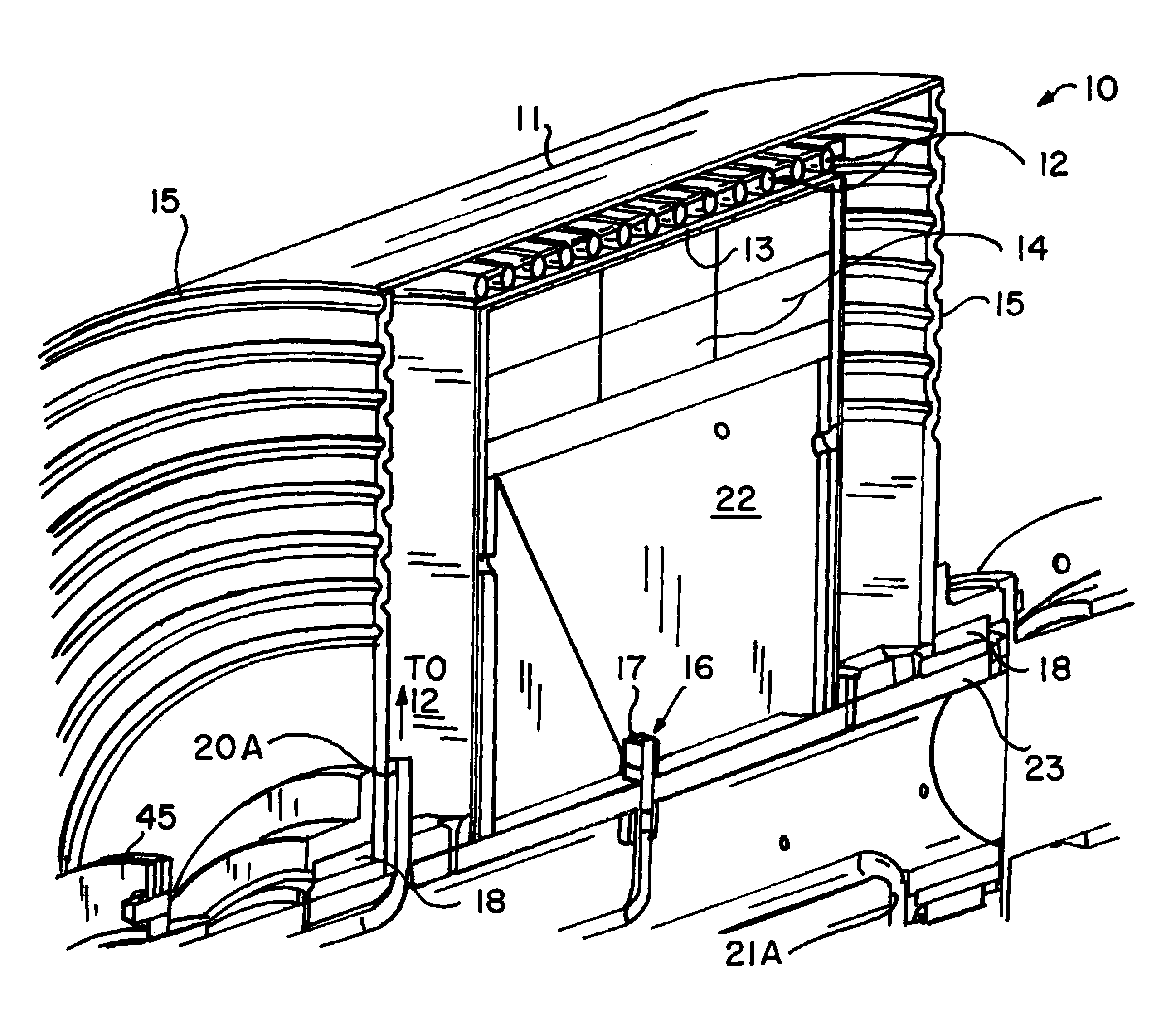
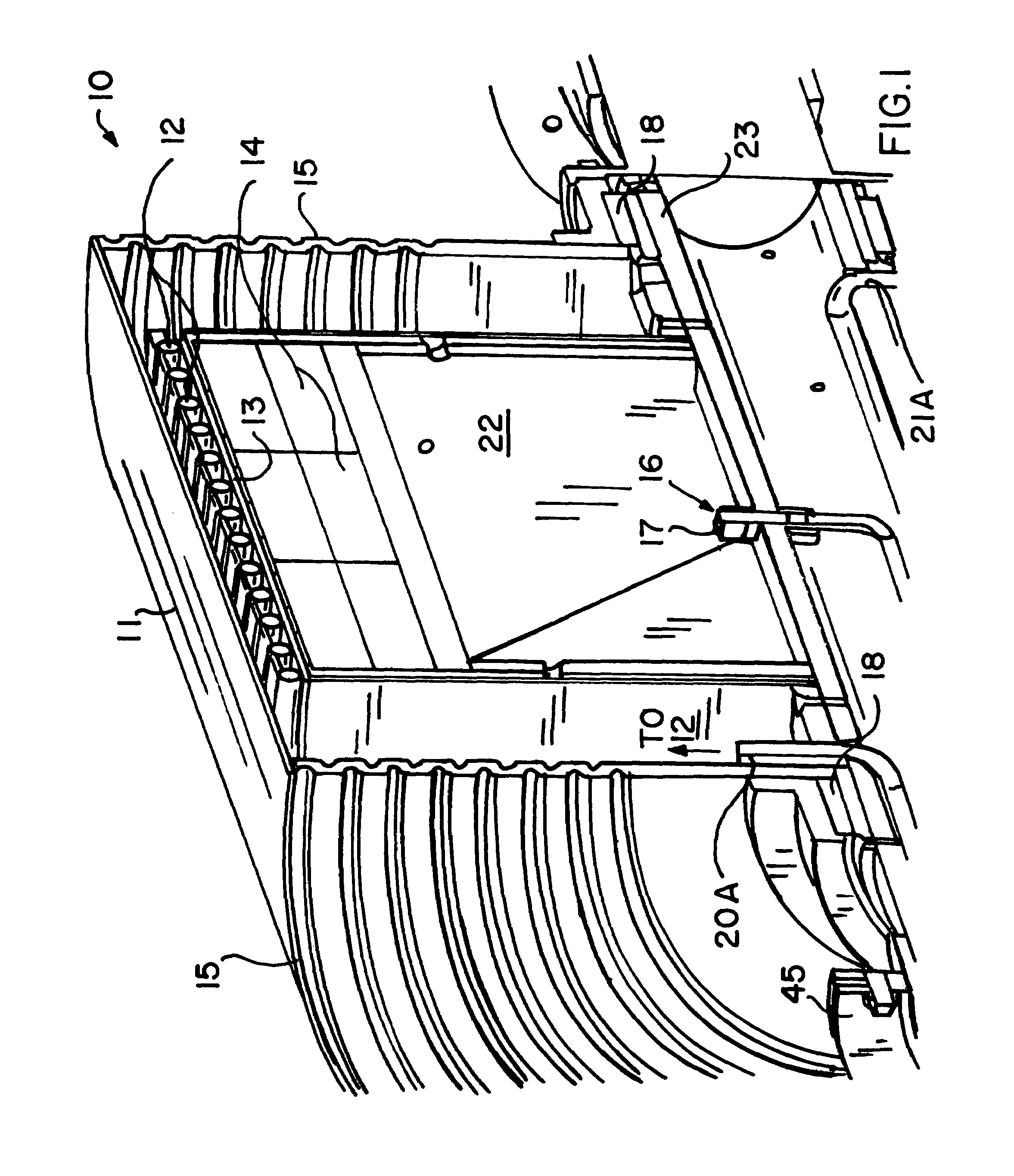
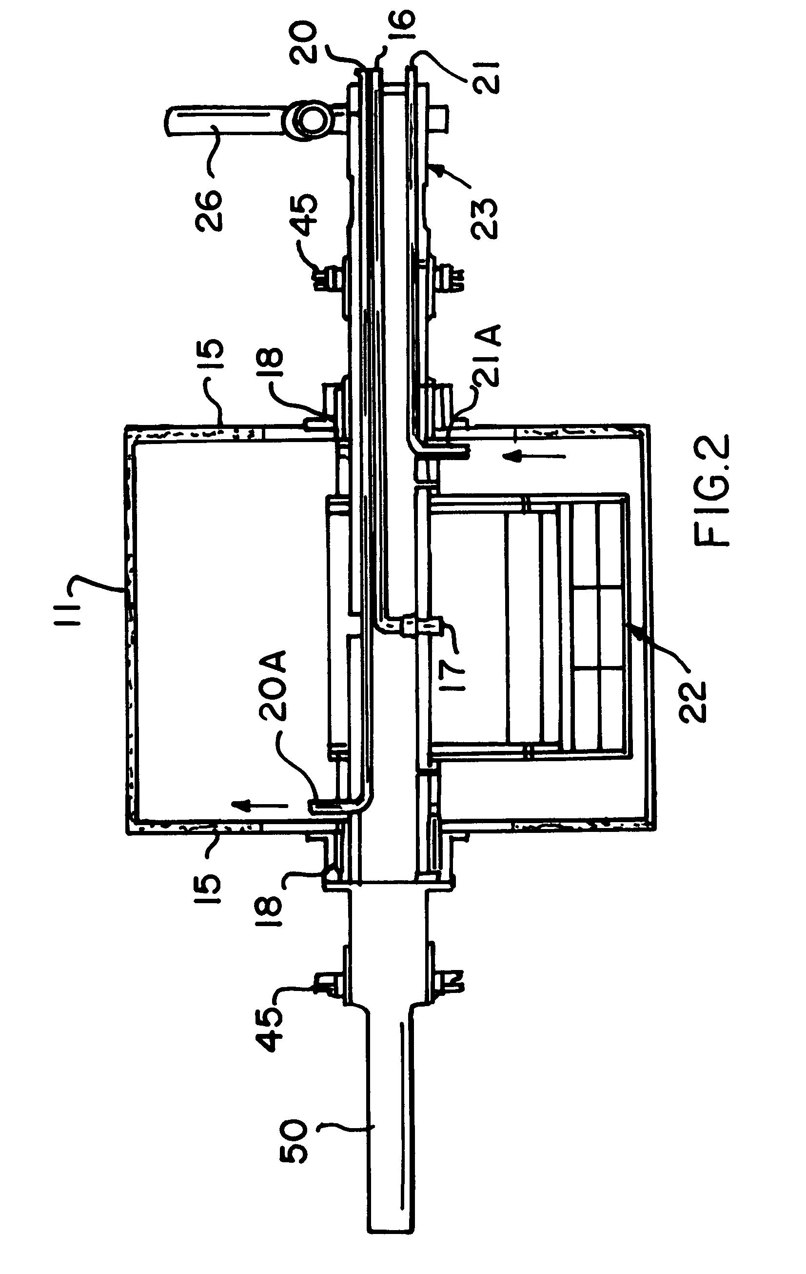
[0045]The present design is known as a Hot Magnetic Separation Process. This process involves controlling important system variables in order to maximize the separation efficiency of magnetic materials using a Hot Magnetic Separator (HMS). The process requires the control of important system variables in order to maximize the separation efficiency of a Hot Magnetic Separator System. One can control the temperature of the sensitive parts of the processing system by controlling the temperature of the feed and the feed rate. Additionally, by controlling the temperature of the feed one can also control the separation performance. Control of feed temperatures enables selective separation of different fractions based on how they respond to a magnetic field as they approach and exceed their Curie temperature. Many of the new design features are similar to a conventional magnetic drum separator, but with the addition of new features to make it capable of sep...


PUM


Abstract

System and method for a continuous process for separating particles according to their magnetic properties such as Curie point includes a feed of hot particles having different magnetic properties on a moving surface spaced above a stationary magnetic assembly. The temperature of the bed of particles is controlled to enable selective separation of different factions of particles based upon the temperature of the particles. The magnets are maintained substantially below their Curie point. Gaseous nitrogen is fed into and from the inside of the magnetic assembly to enhance the cooling of the magnetic assembly and to inhibit oxidation. The gas exits through high temperature bearings to inhibit debris therein. A thermal shield is placed between the moving surface and the magnets and below tubes carrying a cooling fluid to maintain magnets substantially below their Curie point. The entire process is contained with an inert gas-purged cabinet.

Description

CROSS-REFERENCE TO RELATED APPLICATION[0001]Not Applicable.STATEMENT REGARDING FEDERALLY SPONSORED RESEARCH OR DEVELOPMENT[0002]Not Applicable.REFERENCE TO A MICROFICHE APPENDIX[0003]Not Applicable.BACKGROUND OF THE INVENTION[0004]1. Field of the Invention[0005]The present invention relates to magnetic separation processes and apparatus and particularly to magnetic separation at elevated temperatures.[0006]2. Related Art[0007]A key shortcoming of traditional magnetic drum separator designs is that the magnets themselves can't survive the elevated temperatures caused by hot material being fed onto the drum, thus the process requires cooling the materials before they can be magnetically separated. The normal limit for many rare earth magnetic drum separators is an operating temperature of 120 degrees Celsius. This area of the industry would need to operate a magnetic separator with feed temperatures in the range of 700 degree Celsius.[0008]There are several temperature points that mus...

Claims


Application Information

Patent Timeline
Patent Type & Authority Patents(United States)
IPC IPC(8): B03C1/00
CPCB03C1/0332B03C1/0337
Inventor GREY, THOMAS J.DIERICKX, SHAWN A.
Owner METSO OUTOTEC (FINLAND) OY
Why Eureka
Try Eureka