
Plasma injector, exhaust gas purifying system and method for injecting reducing agent

a technology of purifying system and injector, which is applied in the direction of machines/engines, combustion-air/fuel-air treatment, and separation processes, etc., can solve the problems of unreacted fuel discharge, unsatisfactory purification of exhaust gas, and insufficient vaporization of reducing agent by merely injecting reducing agen

Inactive Publication Date: 2009-01-27
TOYOTA JIDOSHA KK
View PDF26 Cites 48 Cited by
  • Summary
  • Abstract
  • Description
  • Claims
  • Application Information

AI Technical Summary

Benefits of technology

The present invention is a plasma injector that can inject a reducing agent in a liquid droplet state and convert it into a plasma for vaporization. This allows for the instantaneous vaporization of the reducing agent and the option of converting it into low molecular weight components with high reactivities. The plasma injector generates a plasma in the vicinity of the injection nozzle, which can be small, resulting in a smaller plasma density with higher energy efficiency. The plasma injector can be used in an exhaust gas purifying system to promote the diffusion of the reducing agent and the contact between the reducing agent and the catalyst, thereby accelerating the reducing reaction on the catalyst and preventing unreacted reducing agent from being exhausted to the atmosphere. The plasma injector can be located at the distal end portion of the injection nozzle, making it easy to generate a plasma in a small area. The plasma generated can be an inductive-coupling plasma, an electric-discharge plasma, or an electric-arcs discharge plasma. The use of an inductive-coupling plasma or a microwave plasma is preferred for durability and to prevent exposure of the electrodes to high temperatures. The exhaust gas purifying system can use a NOx purifying catalyst, such as a NOx storage-reduction catalyst or a NOx selective-reduction catalyst. The plasma injector can be used in the exhaust gas purifying system to accelerate the NOx reduction reaction on the catalyst.

Problems solved by technology

However, in any of these applications, there is a problem that a reducing agent can not be sufficiently vaporized by merely injecting the reducing agent, especially in a low temperature atmosphere.
If a reducing agent, which is injected into an exhaust pipe through which an exhaust gas from an internal combustion engine flows, is insufficiently vaporized, diffusion of the reducing agent to a catalyst, and the contact between the reducing agent and a catalyst, become insufficient, and thereby purification of the exhaust gas cannot be sufficiently achieved, and unreacted fuel may be discharged to the atmosphere.
However, when a fuel is injected into an exhaust gas and then a plasma is generated at the region where the exhaust gas is purified, as per this patent publication document, a large amount of energy is required to a generate plasma and the plasma density obtained thereby becomes small, because all of an exhaust gas flow is converted into a plasma.

Method used


Image

  • Plasma injector, exhaust gas purifying system and method for injecting reducing agent
  • Plasma injector, exhaust gas purifying system and method for injecting reducing agent
  • Plasma injector, exhaust gas purifying system and method for injecting reducing agent

Examples


Embodiment Construction

[0039]The present invention is specifically described below based on the embodiments shown in the Figures. Each Figure schematically shows the present invention, but the present invention is not limited to the embodiments.

[0040]

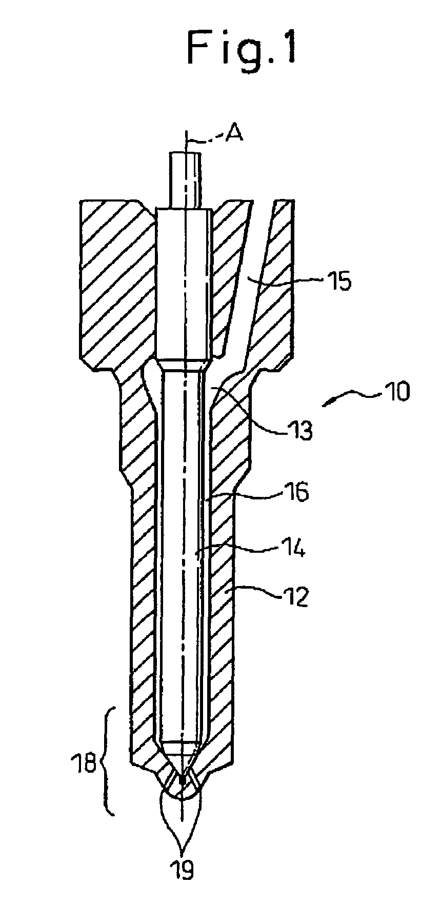
[0041]The plasma injector of the present invention is schematically described with reference to FIG. 2.

[0042]The plasma injector of the present invention can at least partially convert an injected reducing agent into a plasma. The plasma can be generated by injecting a reducing agent from a injection port 19 at the distal end portion 18 of an injection nozzle to a plasma region, particularly to a plasma region in the vicinity of the injection port 19.

[0043]A reducing agent to be injected by the injector of the present invention can be arbitrarily selected depending on usage. The reducing agent includes a hydrocarbon such as gasoline and a light oil, an ether, and an alcohol. Incidentally, the term “reducing agent” means a substance which is supplied from an i...


PUM


Abstract

The present invention provides a plasma injector wherein a reducing agent injected from an injection port (19) at the distal end portion of an injection nozzle (18) is at least partially converted into a plasma; an exhaust gas purifying system; and a method for injecting a reducing agent. Using the plasma injector, the exhaust gas purifying system, and the method for injecting a reducing gas of the present invention, it is possible to vaporize a reducing agent supplied in an injection manner and / or to provide a highly reactive reducing agent from the reducing agent.

Description

TECHNICAL FIELD[0001]The present invention relates to an injector for injecting a reducing agent, an exhaust gas purifying system wherein a reducing agent is injected upstream of a catalyst in an exhaust pipe, and a method for injecting a reducing agent in a liquid state.RELATED ART[0002]FIG. 1 shows a conventional injector which is used for directly injecting a fuel into a combustion chamber of an internal combustion engine. The injector 10 comprises a nearly cylindrical nozzle 12 having a hollow space 13 therein, and a nearly columnar needle valve 14 which slides (moves) in the hollow space 13 in the nozzle 12. The nozzle 12 and the needle valve 14 are disposed such that their axial lines “A” are coaxial. The nozzle 12 is provided with a supply passage 15 communicating with the hollow space 13. The supply passage 15 is connected to a fuel source (not shown), and high-pressure fuel is supplied into the hollow space 13 through the supply passage 15. The fuel to be supplied flows to ...

Claims


Application Information

Patent Timeline
Patent Type & Authority Patents(United States)
IPC IPC(8): F01N3/00F02B23/00F01N3/01F01N3/08F01N3/20F01N3/28F01N3/36F02M27/04F02M51/06F02M69/00
CPCB01D53/90B01D53/925F01N3/2066F01N3/36B01D2259/818F01N2240/28F01N2570/14F01N2610/03F01N2610/1453Y02T10/24Y02T10/12
Inventor HIRATA, HIROHITOMATSUMURA, ERIKO
Owner TOYOTA JIDOSHA KK
Learn More