Eureka AIR delivers breakthrough ideas for toughest innovation challenges, trusted by R&D personnel around the world.

Encapsulated covered stent

a covered stent and encapsulation technology, applied in the field of encapsulated covered stents, can solve the problems of thrombotic complications, large profile, restnosis, etc., and achieve the effect of reducing the risk of thrombotic complications

Inactive Publication Date: 2009-01-27
ABBOTT CARDIOVASCULAR
View PDF368 Cites 27 Cited by
  • Summary
  • Abstract
  • Description
  • Claims
  • Application Information

AI Technical Summary

Benefits of technology

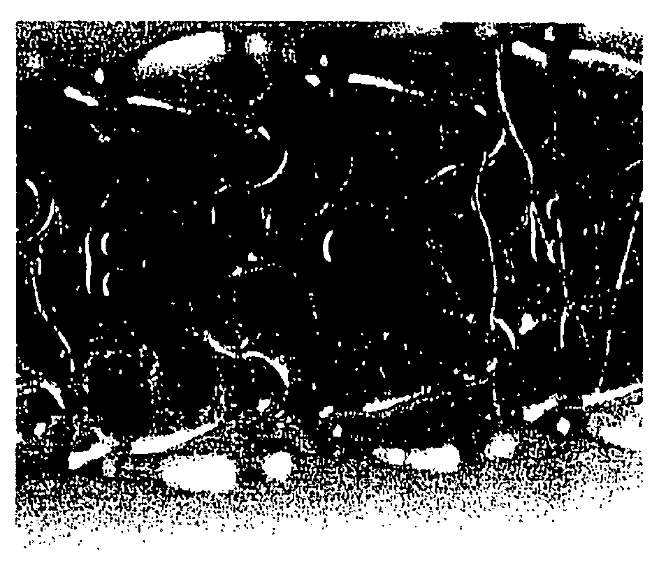
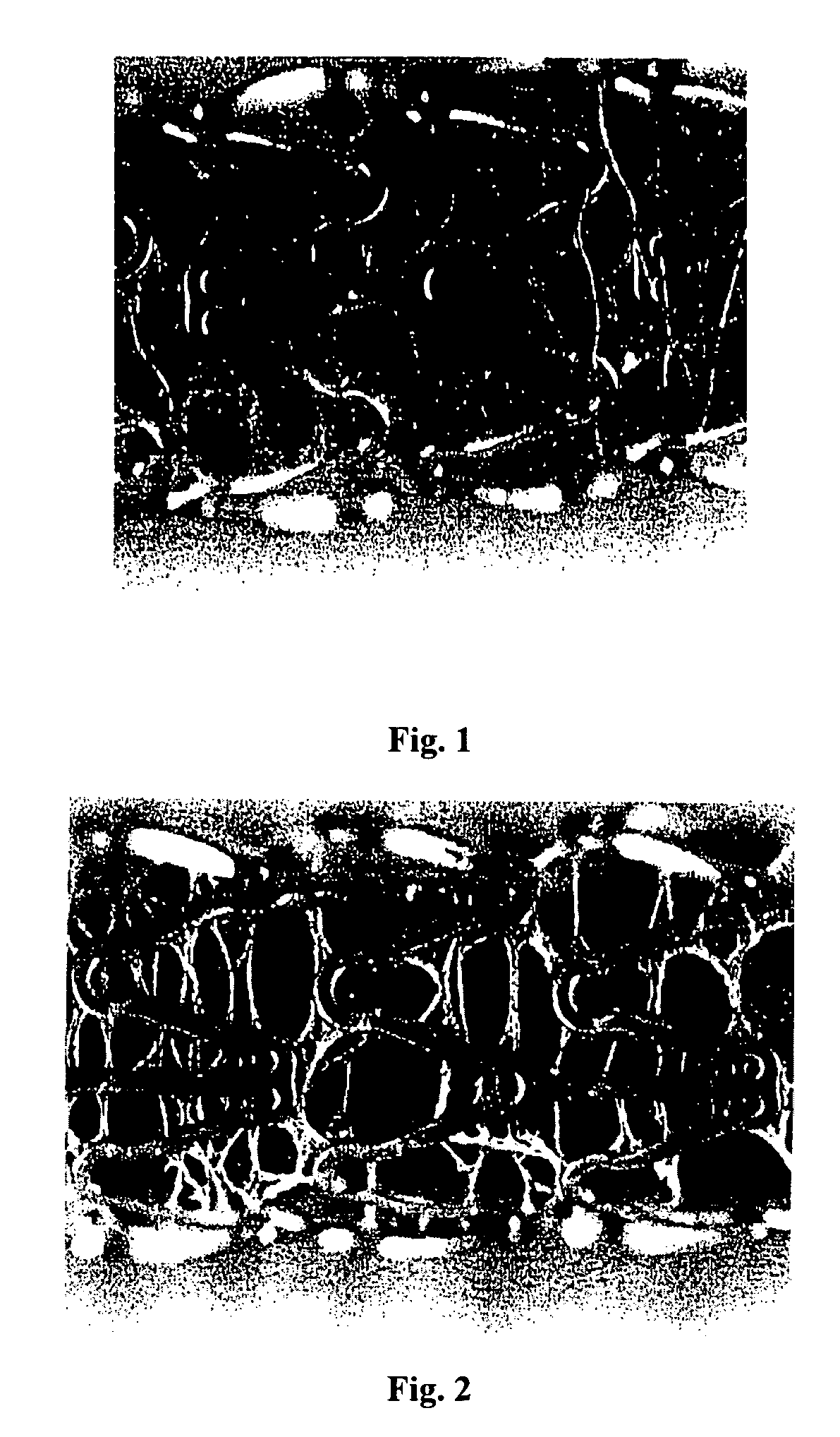
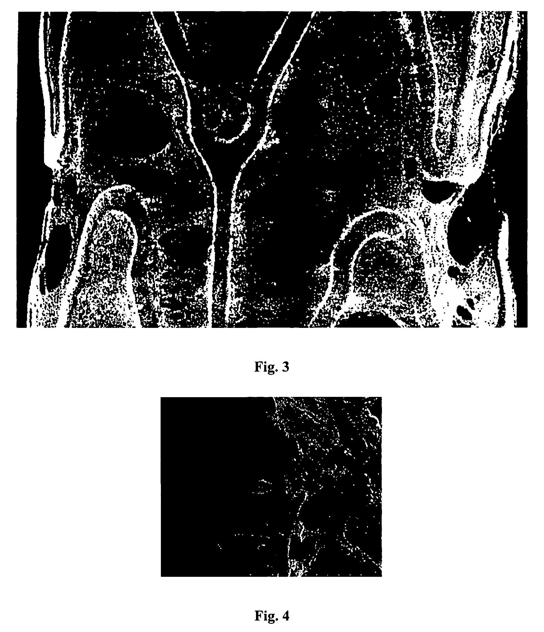
The invention is about making medical devices with a lattice structure created by cutting out implantable portions of the device. The cutouts have polymer filaments between them, which can be coated or introduced with drugs. The filaments can be 0.1-100 μm in diameter. The degree of covering of the openings formed by the cutouts can be 10-90%. The device can be a stent, and certain processing parameters can be modified to cause filament formation or cobwebbing between the stent struts. The invention also includes using solvents of lower boiling point, increasing the concentration of polymer in solution, increasing the spray nozzle and dry nozzle temperatures, increasing the spray flow rate, increasing the atomization pressure, decreasing the surface-tension parameter, and increasing the stent rotation speed.

Problems solved by technology

But since stents can cause biological responses that precipitate in-stent restenosis, or thrombosis skilled artisans want biologically invisible stents, which tends toward low wall coverage.
Their mechanical limitations center on their deliverability and larger profile compared to regular stents.
Biological challenges include not only restenosis, but also a higher incidence of thrombotic complications due to the larger surface area of synthetic material.
There is a place for covered stents in interventional cardiology but they still have the following issues:The covering increases the stent profile because it lies on the stent's outer surfaces so it is external to the stent;The covering must expand with the stent; tearing is possible if the covering is not sufficiently elastic;Attachment of the covering to the stent is problematic; insecure attachment can lead to the covering becoming loose or folding over;A covered stent that is too impermeable can completely isolate the underlying endothelium / smooth muscle from its blood supply, which can cause tissue death or necrosis.

Method used


Image

  • Encapsulated covered stent
  • Encapsulated covered stent
  • Encapsulated covered stent

Examples


example 1

[0102]A first composition was prepared by mixing the following components:[0103]about 2 mass % Kynar Flex 2800;[0104]dissolved in a mixture of acetone, dioxane, and Techspray at a weight ratio of 25 / 50 / 25

[0105]The first composition was applied onto the surface of a bare 13 mm TETRA stent (available from Guidant Corporation) by spraying and dried to form a cobwebbed stent coating. A spray coater was used, having a 0.014 round nozzle maintained at ambient temperature with a feed pressure of about 0.2 atm (about 3 psi) and an atomization pressure of about 15 psi (about 1.02 atm). The spray nozzle temperature was at ambient and a coating rate of 0.2 μg / mm sec of the wet coating was applied per pass. Between the passes, the coating was dried at using a flow of ambient temperature air for about 10 seconds. A total of 20 passes were applied. Following the last pass, the coating was baked at about 50° C. for about 2 hours. This yielded a cobwebbed, covered stent coating containing about 330...

example 2

[0106]A first composition was prepared by mixing the following components:[0107]about 2 mass % Solef 11010;[0108]dissolved in a mixture of acetone, dioxane, and Techspray at a weight ratio of 50 / 25 / 25

[0109]The first composition was applied onto the surface of a bare 13 mm TETRA stent (available from Guidant Corporation) by spraying and dried to form a cobwebbed stent coating. A spray coater was used, having a 0.014 round nozzle maintained at ambient temperature with a feed pressure of about 0.2 atm (about 3 psi) and an atomization pressure of about 15 psi (about 1.02 atm). The spray nozzle temperature was at ambient and a coating rate of 0.23 μg / mm sec of the wet coating was applied per pass. Between the passes, the coating was dried at using a flow of ambient temperature air for about 10 seconds. A total of 20 passes were applied. Following the last pass, the coating was baked at about 50° C. for about 2 hours. This yielded a cobwebbed, covered stent coating containing about 347 μg...


PUM

PropertyMeasurementUnit
diameteraaaaaaaaaa
average diameteraaaaaaaaaa

Abstract

This disclosure provides a description of medical devices with polymeric cobwebbing disposed near the surfaces of the medical device. This cobwebbing can contain drug(s) and can enhance the mechanical and chemical function of intraluminal stents. Methods of using these devices and methods of preparing the devices are disclosed, as well.

Description

DESCRIPTION OF THE BACKGROUND[0001]Physicians commonly treat blood vessel occlusions by mechanically enhancing blood flow in the affected vessels, such as by employing a stent. Stents act as scaffoldings, physically holding open and, if desired, expanding the wall of affected vessels. Typically, stents can compress for insertion through small lumens via catheters and then expand to a larger diameter once they are positioned. Examples in the patent literature disclosing stents include U.S. Pat. No. 4,733,665 issued to Palmaz, U.S. Pat. No. 4,800,882 issued to Gianturco, and U.S. Pat. No. 4,886,062 issued to Wiktor.[0002]Physicians also use stents for providing biological therapy by medicating the stents. Medicated stents allow local administration of a drug. This is preferred because these stents concentrate the drug at a specific site and thus deliver smaller total medication levels in comparison to systemic dosages.[0003]One stent medicating method involves using a coating of a pol...

Claims


Application Information

Patent Timeline
Patent Type & Authority Patents(United States)
IPC IPC(8): A61F2/06
CPCA61F2/91A61L31/10A61L31/16A61F2250/0067A61L2300/60Y10S623/901
Inventor PACETTI, STEPHEN DIRKLE, HUNG MANHANDREACCHI, ANTHONYGADA, MANISH
Owner ABBOTT CARDIOVASCULAR
Why Eureka
Eureka Blog
Learn More