Light trapping in thin film solar cells using textured photonic crystal

a technology of photonic crystals and solar cells, applied in the field of solar cells, can solve the problems of very limited arrangement of essentially using the light received for direct photovoltaic purposes

Inactive Publication Date: 2009-01-27
MASSACHUSETTS INST OF TECH
View PDF2 Cites 44 Cited by
  • Summary
  • Abstract
  • Description
  • Claims
  • Application Information

AI Technical Summary

Problems solved by technology

Such arrangement is very limited in essentially using the light received for direct photovoltaic purposes.

Method used


Image

  • Light trapping in thin film solar cells using textured photonic crystal
  • Light trapping in thin film solar cells using textured photonic crystal
  • Light trapping in thin film solar cells using textured photonic crystal

Examples


Embodiment Construction

[0015]The invention utilizes a photonic microstructure, in conjunction with thin silicon solar cells in order to enhance cell efficiency. The structure should increase the optical path length of wasted photons by creating anomalous refraction effects.

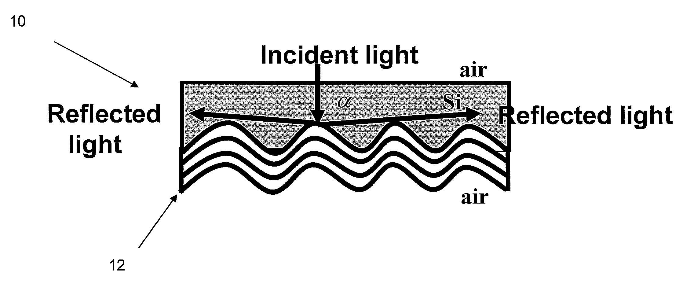
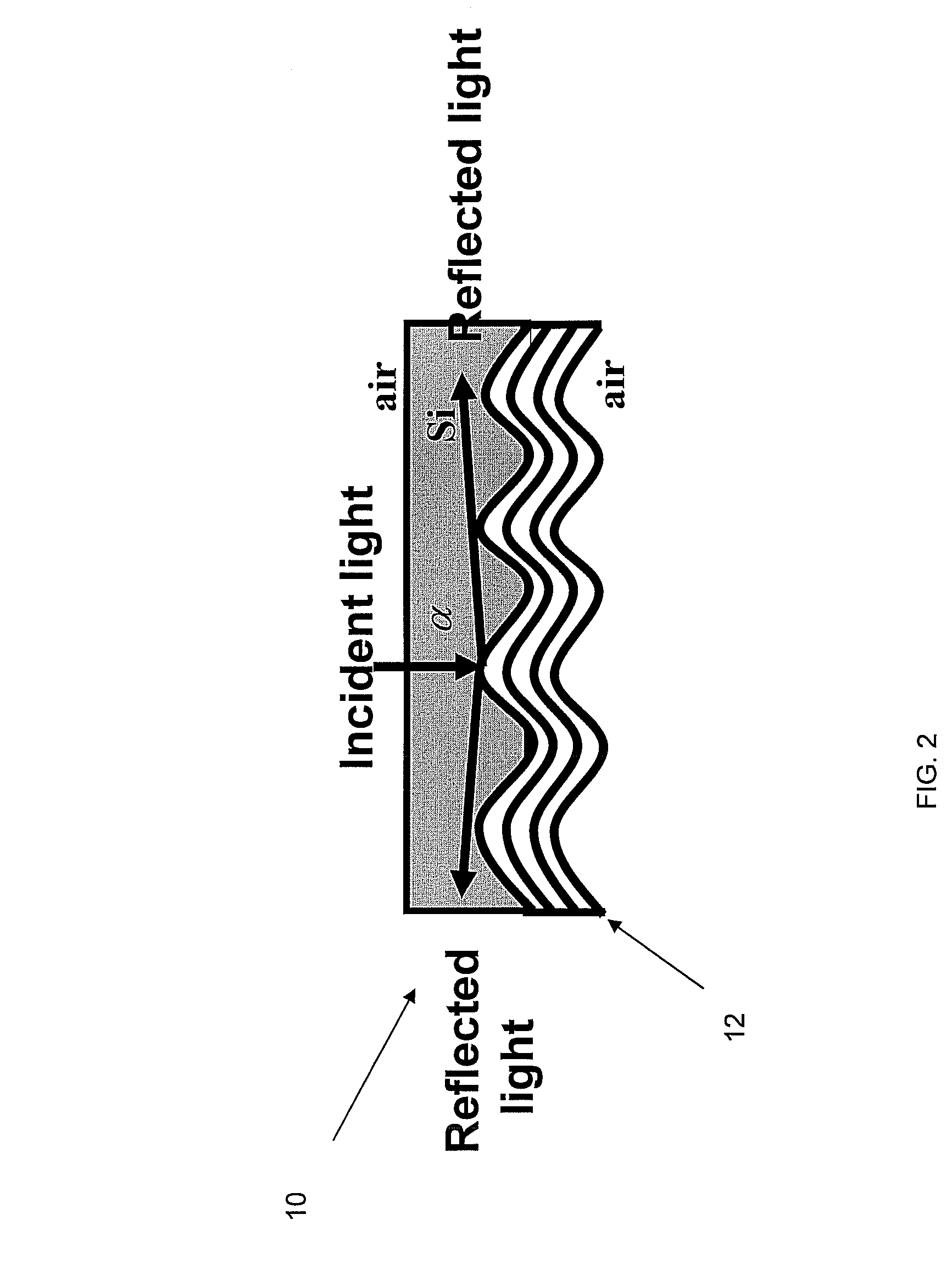
[0016]In order to improve thin film solar cell efficiency, the invention uses a light-trapping scheme that can tremendously enhance optical path length and make light almost completely absorbed by using novel photonic structure on the backside reflector.

[0017]The invention utilizes a photonic structure to trap light. This arrangement would allow strong light bending so that reflected light is almost in the parallel direction of the absorption layer.

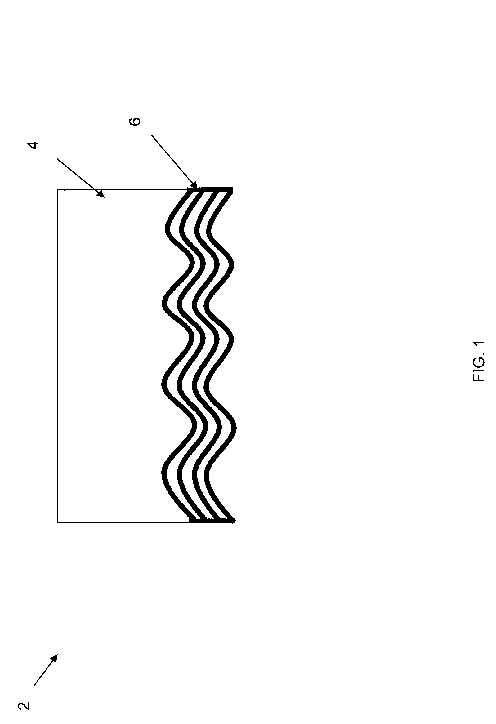
[0018]FIG. 1 illustrates a solar cell structure 2 that includes a backside reflector structure 6. Solar cell 2 is preferably a thin Si solar cell. Solar cell 2 has a photoactive region 4 with a wavered backside reflector 6 formed, for example, from wavered DBR gratings. Any incident wave in t...


PUM


Abstract

A solar cell includes a photoactive region that receives light. A photonic crystal is coupled to the photoactive region, wherein the photonic crystal comprises a distributed Bragg reflector (DBR) for trapping the light.

Description

PRIORITY INFORMATION[0001]This application claims priority from provisional application Ser. No. 60 / 645,766 filed Jan. 19, 2005.[0002]This invention was made with government support under National Renewable Energy Laboratory Subcontract Number XAT-2-31605-07, awarded by the Department of Energy. The government has certain rights to the invention.BACKGROUND OF THE INVENTION[0003]The invention relates to the field solar cells, in particular to photonic microstructure used in conjunction with solar cells.[0004]Photovoltaic cells, commonly known as solar cells, are well known devices that convert light energy into electricity. Solar cells provide a number of advantages when compared to conventional energy sources. For example, solar cells produce electricity without pollution and do not use the dwindling fossil fuel supply.[0005]Silicon is one of the most popular materials for making solar cells. A silicon solar cell is conventionally created by doping the silicon to form an n-type laye...

Claims


Application Information

Patent Timeline
Patent Type & Authority Patents(United States)
IPC IPC(8): H01L31/00
CPCB82Y20/00G02B6/1225H01L31/056H01L31/0232Y02E10/52
Inventor YI, YASHAKIMERLING, LIONEL C.DUAN, XIAOMANZENG, LIRONG
Owner MASSACHUSETTS INST OF TECH
Why Eureka
Try Eureka