
Discharge lamp ballast with detection of abnormal discharge outside the arc tube

a discharge lamp and ballast technology, applied in the direction of electric variable regulation, process and machine control, instruments, etc., can solve the problems of abnormal arc discharge, undue stress on the lamp, abnormal arc discharge, etc., and achieve the effect of enabling the safe operation of the discharge lamp

Inactive Publication Date: 2009-01-27
MATSUSHITA ELECTRIC WORKS LTD
View PDF8 Cites 5 Cited by
  • Summary
  • Abstract
  • Description
  • Claims
  • Application Information

AI Technical Summary

Benefits of technology

"The present invention provides a novel discharge lamp ballast that can identify and limit abnormal arc discharges outside of the arc tube, ensuring safe operation of the discharge lamp. The ballast includes an igniter for starting the discharge lamp and an AC power unit for operating it after ignition. A detector is included to examine the electrical characteristics of the arc discharge and determine if it is abnormal. The detector analyzes the electrical characteristic of the arc discharge and provides different logics for determining abnormal discharge. The ballast can limit the AC output power to the arc tube and detect the abnormal discharge to alert the operator and take appropriate action."

Problems solved by technology

However, this advantage may sometimes cause the lamp to suffer from undue stress which would deteriorate an arc tube of the discharge lamp.
Once the leakage becomes critical, an abnormal arc discharge would occur within an envelop surrounding the arc tube when supplying the AC output power to the arc tube.
That is, the abnormal arc discharge would develop between an electrode of the arc tube and a certain conductive part within the envelope.
If such abnormal arc discharge continues, the discharge lamp would be damaged.
Also, if there be any discontinuity in the electric feeding line from the ballast to the discharge lamp due to the disconnection or a dielectric breakage in a covering of the feeding line, like abnormal arc discharge would develop in the feeding line, thereby damaging the ballast, the connection, and / or the discharge lamp itself.

Method used


Image

  • Discharge lamp ballast with detection of abnormal discharge outside the arc tube
  • Discharge lamp ballast with detection of abnormal discharge outside the arc tube
  • Discharge lamp ballast with detection of abnormal discharge outside the arc tube

Examples


Embodiment Construction

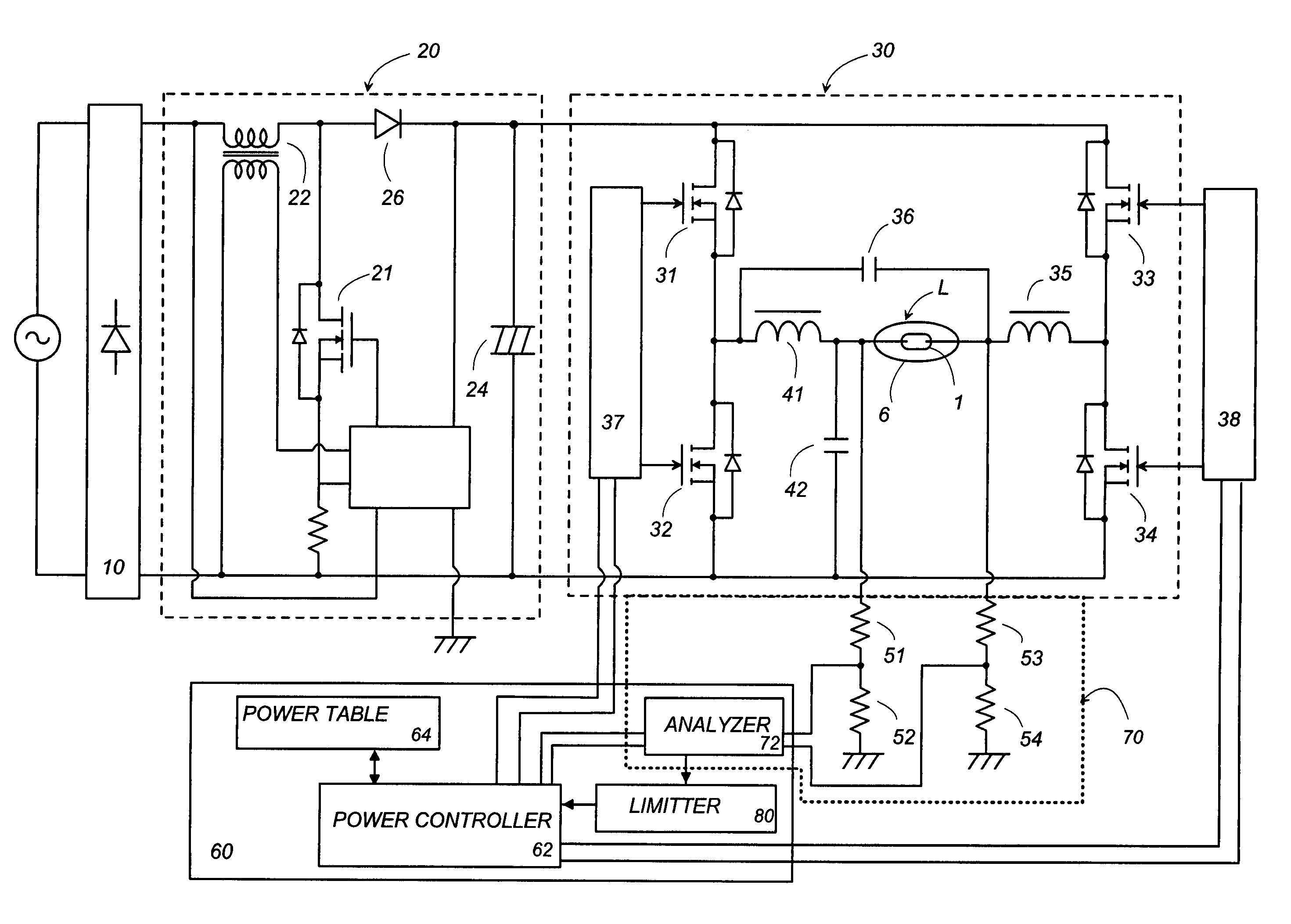
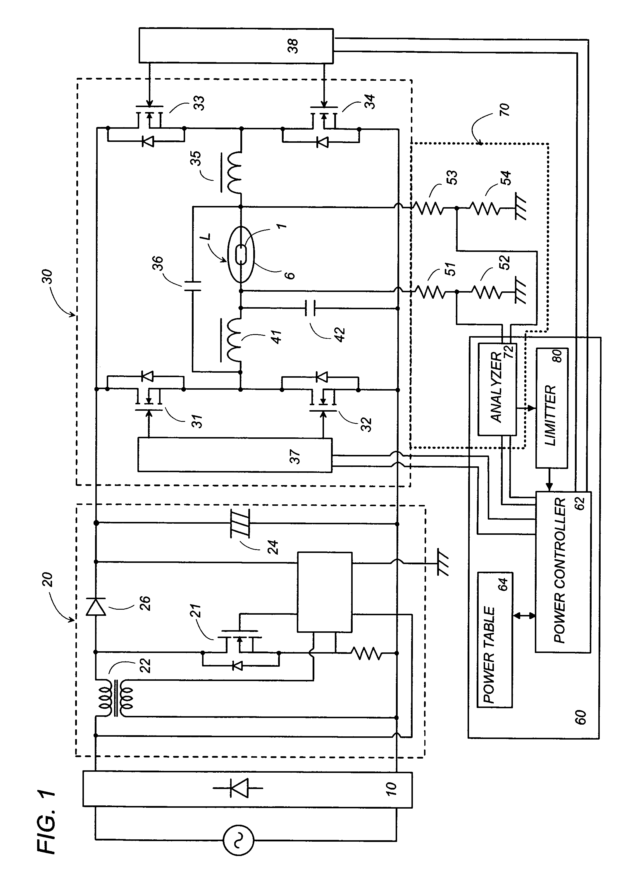
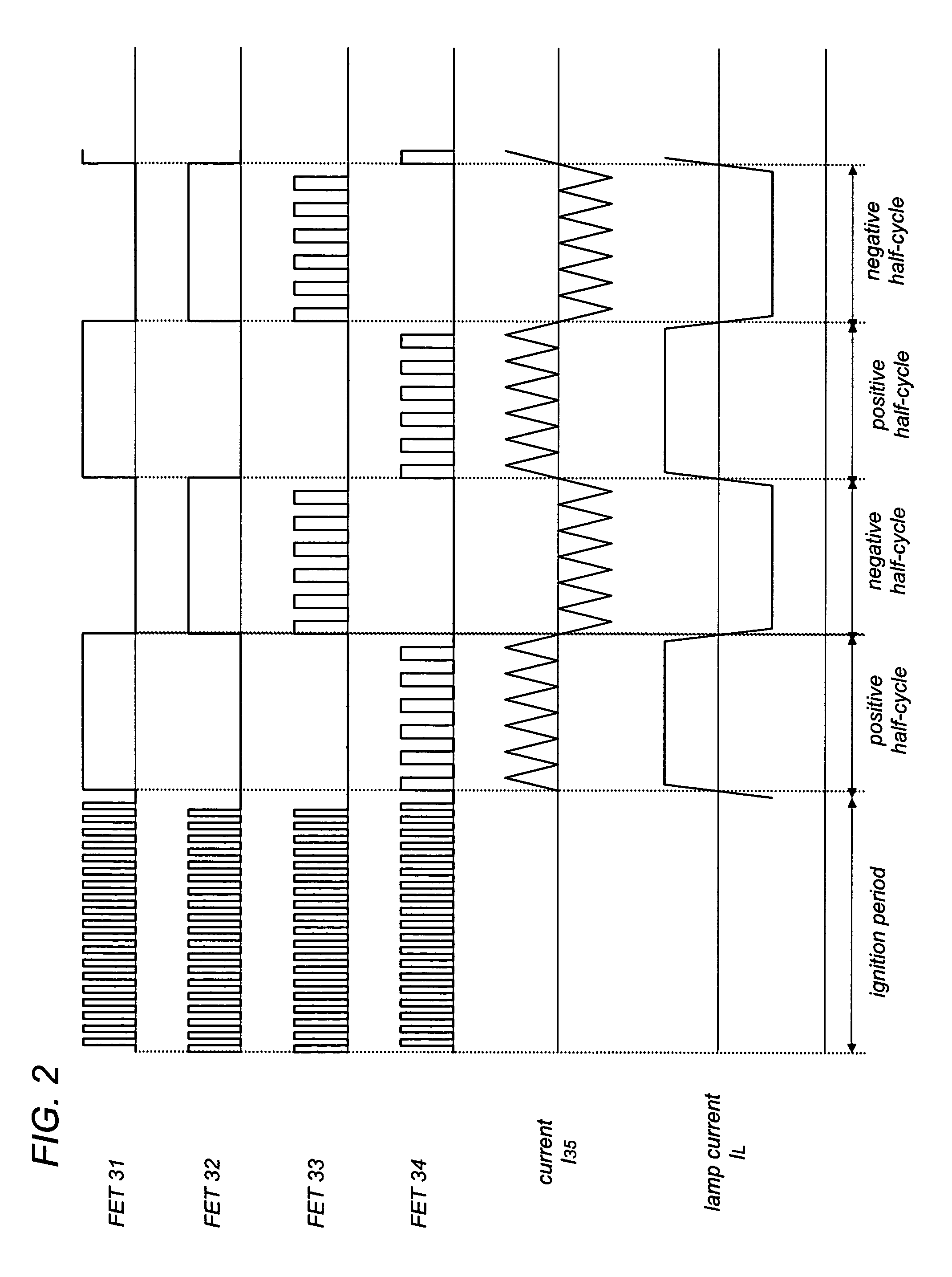
[0020]Now referring to FIG. 1, there is shown a circuit diagram of a discharge lamp ballast according to the preferred embodiment of the present invention. The ballast is designed to operate a discharge lamp, particularly a high-intensity discharge lamp L composed of an arc tube 1 and an envelope 6 surrounding the arc tube. The arc tube 1 is filled with a metal halide in addition to the mercury and an inert gas, while the envelope 6 is evacuated. The ballast includes a rectifier 10 that provides a DC voltage from an AC voltage source, a DC-DC converter 20 that converts the rectified DC voltage into a smoothed DC voltage, and an inverter 30 that provides a low frequency AC output power or voltage to the discharge lamp L. The DC-DC converter 20 is of a type known as a step-up chopper including a switching transistor 21 connected in series with an inductor 22 across the rectifier 10, and a smoothing capacitor 24 connected in series with a diode 26 across the switching transistor 21. Th...


PUM


Abstract

A discharge lamp ballast is designed to limit or interrupt its AC output power to the discharge lamp upon occurrence of an abnormal discharge outside of an arc tube. A detector is included to examine a lamp voltage once in each of the positive and negative half-cycles or in each one complete cycle of the AC output power, and identifies the abnormal discharge when there is a particular change in the monitored lamp voltage. The particular change may be defined by a single logic or by combination of several logics each designed to represent specific characteristic for the abnormal discharges of several types.

Description

TECHNICAL FIELD[0001]The present invention is directed to a discharge lamp ballast, and more particularly to an electronic lamp ballast that detects an abnormal arc discharge occurring outside of an arc tube for limiting or interrupting an AC output power being fed to the discharge lamp upon detection of the abnormal arc discharge.BACKGROUND ART[0002]An electronic discharge lamp ballast has been accepted as having an inherent capability of providing a relatively high re-ignition voltage to a discharge lamp reaching its near end of lamp life for prolonging the lamp life. However, this advantage may sometimes cause the lamp to suffer from undue stress which would deteriorate an arc tube of the discharge lamp. The typical deterioration is a leakage of a filling gas out of the arc tube. Once the leakage becomes critical, an abnormal arc discharge would occur within an envelop surrounding the arc tube when supplying the AC output power to the arc tube. That is, the abnormal arc discharge...

Claims


Application Information

Patent Timeline
Patent Type & Authority Patents(United States)
IPC IPC(8): G05F1/00H05B41/292H05B41/24
CPCH05B41/2921H05B41/2925Y10S315/05
Inventor FUKUDA, KENICHIYAMASHITA, KOUJI
Owner MATSUSHITA ELECTRIC WORKS LTD
Learn More