Method and system for link-based clock synchronization in asynchronous networks

a technology of asynchronous networks and clocks, applied in the field of clock synchronization in networks, can solve the problems of complex timing problems difficult to properly utilize synchronous data at the receiving network device, and disadvantages of asynchronous networks when used to transmit synchronous or real-time data

Inactive Publication Date: 2009-01-27
RPX CLEARINGHOUSE
View PDF16 Cites 60 Cited by
  • Summary
  • Abstract
  • Description
  • Claims
  • Application Information

AI Technical Summary

Benefits of technology

[0016]The present invention will now be described in more detail with reference to exemplary embodiments thereof as shown in the appended drawings. While the present invention is described below with reference to preferred embodiments, it should be understood that the present invention is not limited thereto. Those of ordinary skill in the art having access to the teachings herein will recognize additional implementations, modifications, and embodiments, as well as other fields of use, which are within the scope of the present invention as disclosed and claimed herein, and with respect to which the present invention could be of significant utility.

Problems solved by technology

However, asynchronous networks often are at a disadvantage when used to transmit synchronous or real-time data.
For one, unlike synchronous networks, asynchronous networks typically have jitter and wander that is unbound, making it difficult for the proper utilization of synchronous data at the receiving network device due to the indeterminate timing of the data.
Additionally, most asynchronous networks do not have an inherent scheme to transmit clock synchronization information throughout the network, further compounding timing issues at receiving network devices.
Packets are often received out of order, dropped, and so on, resulting in an output sound quality that is less than optimal.
Since such asynchronous networks typically do inherently implement a clock synchronization signal, the output sound quality is further degraded due to the variation in the operation of the clock at the source network device and the clock at the receiving network device.
Such variation can cause the receiving network device to output the sample sooner and / or later than intended, resulting in clipped or garbled audio output.
However, the link 176, being an asynchronous data link (e.g., Ethernet), typically does not provide for synchronization with the clock reference signal.
However, due to the transmission time dispersion prevalent in packet-based networks, these clock-recovery algorithms often are inaccurate, thereby affecting the processing of the synchronous data at the receiving network device.
However, GPS-based clock synchronization techniques have a number of limitations.
For one, the GPS-based clock synchronization systems often are cost-prohibitive due to the expense of the GPS receivers.
Also, problems may arise when the network device is located within a building or otherwise does not have a line-of-sight with a GPS satellite, making it difficult if not impossible for the GPS receiver of the network device to receive a GPS signal from which the timing reference is to be extracted.
This technique requires specialized packet traffic engineering and, by doing so, increases the complexity of the management procedures.
Additionally, by assigning each adapter to a specific portion of the frame, the benefits of asynchronous transmission / reception are lost.

Method used


Image

  • Method and system for link-based clock synchronization in asynchronous networks
  • Method and system for link-based clock synchronization in asynchronous networks
  • Method and system for link-based clock synchronization in asynchronous networks

Examples


Embodiment Construction

)

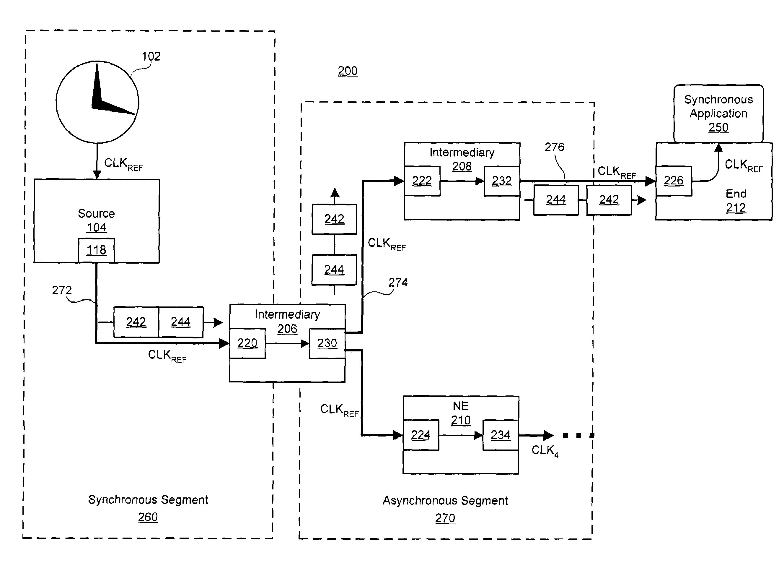
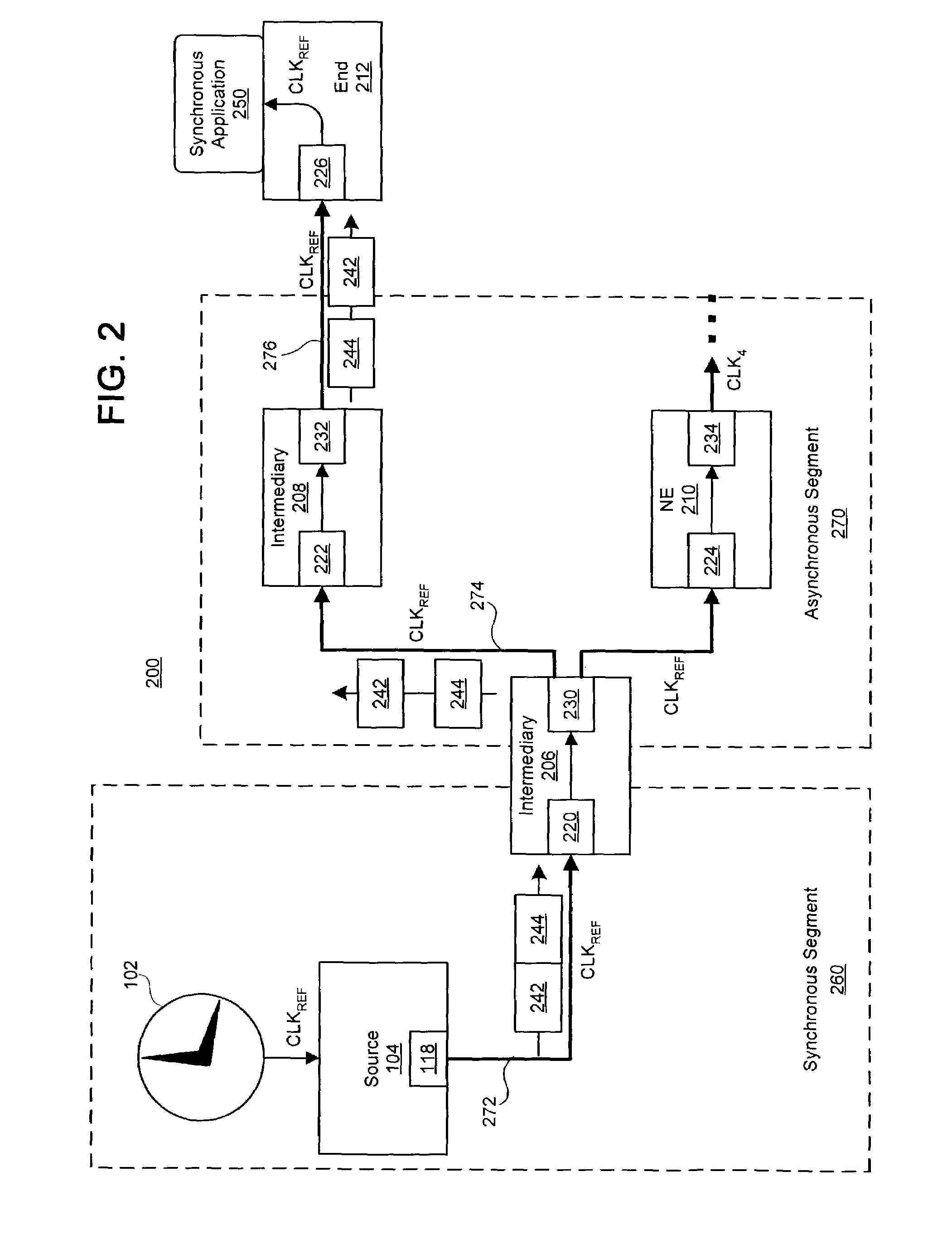
[0023]FIGS. 2-6 illustrate exemplary techniques and systems for clock synchronization in networks having one or more asynchronous data links. In at least one embodiment, a clock signal is propagated at the physical layer of asynchronous data link(s) between a source network device and a destination network device. Each device between the source network device and the destination network device, in one embodiment, is adapted to receive an incoming clock signal from a previous network device and then provide a signal synchronized to the incoming clock signal to the next network device. At the same time, each network device of the asynchronous segments of the network can continue to transmit packets of data asynchronously. By locking the link-based frequency on a per link-basis, the receiver clocks located at the edge of a network can be directly tied to a primary source located in the core network.

[0024]Clock synchronization techniques in accordance with at least one embodiment of th...


PUM


Abstract

A system and method for clock synchronization in a network having one or more asynchronous data links is provided. A clock signal is propagated through, at the physical layer, a sequence of network devices linking a source network device to a destination network device of the network. Each asynchronous data link between the source network device and the destination network device is adapted to receive an incoming clock signal from the previous network device and then provide a clock signal synchronized to the received clock signal to the next network device of the sequence. At the same time, each network device of an asynchronous segment of the network can continue to transmit packets of data asynchronously. By locking the link-based frequency on a per link bases, the receiver clocks located at the edge of a network can be tied directly to a primary source located in the core network.

Description

CROSS-REFERENCE TO RELATED APPLICATIONS[0001]Priority is claimed based on U.S. Provisional Application No. 60 / 362,809 entitled “OE Sync / Clock Distribution” filed on Mar. 8, 2002.FIELD OF THE INVENTION[0002]The present invention relates generally to clock synchronization in networks and, more particularly, to a technique for clock synchronization in asynchronous and hybrid networks.BACKGROUND OF THE INVENTION[0003]Asynchronous networks, such as Ethernet networks, increasingly are being used to transmit real-time, synchronous, and / or time-sensitive data. To illustrate, wireless carriers often implement fiber-optic based Ethernet (“Optical Ethernet”) networks to transmit voice data to / from a central office (CO) or point-of-presence (POP) to base transceiver stations. Likewise, various circuit emulation protocols for packet-based networks, such as Voice over Internet Protocol (VoIP), are commonly used to transmit real-time voice data over packet-switched networks.[0004]These asynchronou...

Claims


Application Information

Patent Timeline
Patent Type & Authority Patents(United States)
IPC IPC(8): H04J3/06H04L7/00
CPCH04J3/0673H04J3/0632H04J3/0644H04J3/0664H04J3/0688H04J2203/0082H04J2203/0087
Inventor GIESE, PETERPENG, WANG-HSINELLIS, DONALD
Owner RPX CLEARINGHOUSE
Why Eureka
Try Eureka