Ink jet head manufacturing method and ink jet head manufactured by the manufacturing method

a manufacturing method and jet head technology, applied in the direction of manufacturing tools, photomechanical devices, instruments, etc., can solve the problems of large amount of energy required for a photodegradation reaction of the positive type resist, sensitivity tends to decrease, and the flow path pattern of the ink flow is dissolved and deformed, so as to prevent the generation of cracks and accelerate the intermolecular crosslinking. , the effect of high throughpu

Inactive Publication Date: 2009-02-03
CANON KK
View PDF22 Cites 17 Cited by
  • Summary
  • Abstract
  • Description
  • Claims
  • Application Information

AI Technical Summary

Benefits of technology

[0011]In view of the foregoing, the invention provides particularly effective, novel means as the method for manufacturing an ink jet head when the high-density ink jet head is manufactured at high throughput. When particularly acrylic resins are used as the positive type resist for forming the flow path, the invention focuses the point that the generation of the crack is prevented by using a specific developing solution, the progress of the intermolecular crosslinking is suppressed as much as possible, and a polarity of a (meta)acrylic resin is controlled by changing a proportion of a (meta)acrylic acid component in the resin, which improves the sensitivity for the developing solution. The invention also focuses the point that the dissolution and deformation of the ink flow path pattern formed by the positive type resist are prevented by using a specific organic solvent as application solvent of the negative type resist and the generation of the crack can be suppressed to coat the ink flow path pattern with the negative type resist.

Problems solved by technology

However, since a negative type resist is applied onto the ink flow path pattern formed by the positive type resist, sometimes there is generated a problem that the ink flow path pattern is dissolved and deformed during the application of the negative type resist.
According to these methods, although the deformation of the ink flow path pattern can be prevented, the following problems still exist:(1) Due to the intermolecular crosslinking, a large amount of energy is required for a photodegradation reaction of the positive type resist, and sensitivity tends to decrease.
Further, because progress of the photodegradation reaction is insufficient, particularly when the positive type resist is used in a thick film, sometimes a decrease in resolution is generated.(2) When the positive type resist is used in the thick film, sometimes a crack is generated by curing shrinkage stress associated with the intermolecular crosslinking.
Further, sometimes the crack is generated in development or in the application of the negative type resist.(3) In order to impart the sufficient solvent-resistance properties, heat treatment is required at high temperatures for a long time.
Therefore, a width or a height of the ink flow path is restricted, which results in not only an obstacle of ink flow path design but also a decrease in production.

Method used


Image

  • Ink jet head manufacturing method and ink jet head manufactured by the manufacturing method
  • Ink jet head manufacturing method and ink jet head manufactured by the manufacturing method
  • Ink jet head manufacturing method and ink jet head manufactured by the manufacturing method

Examples


example 1

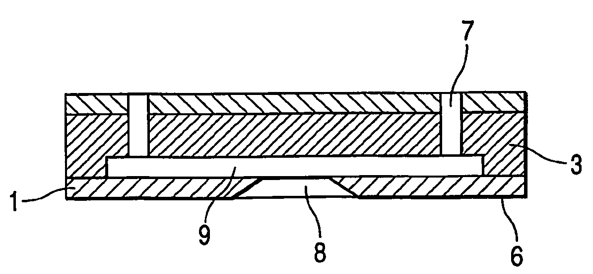
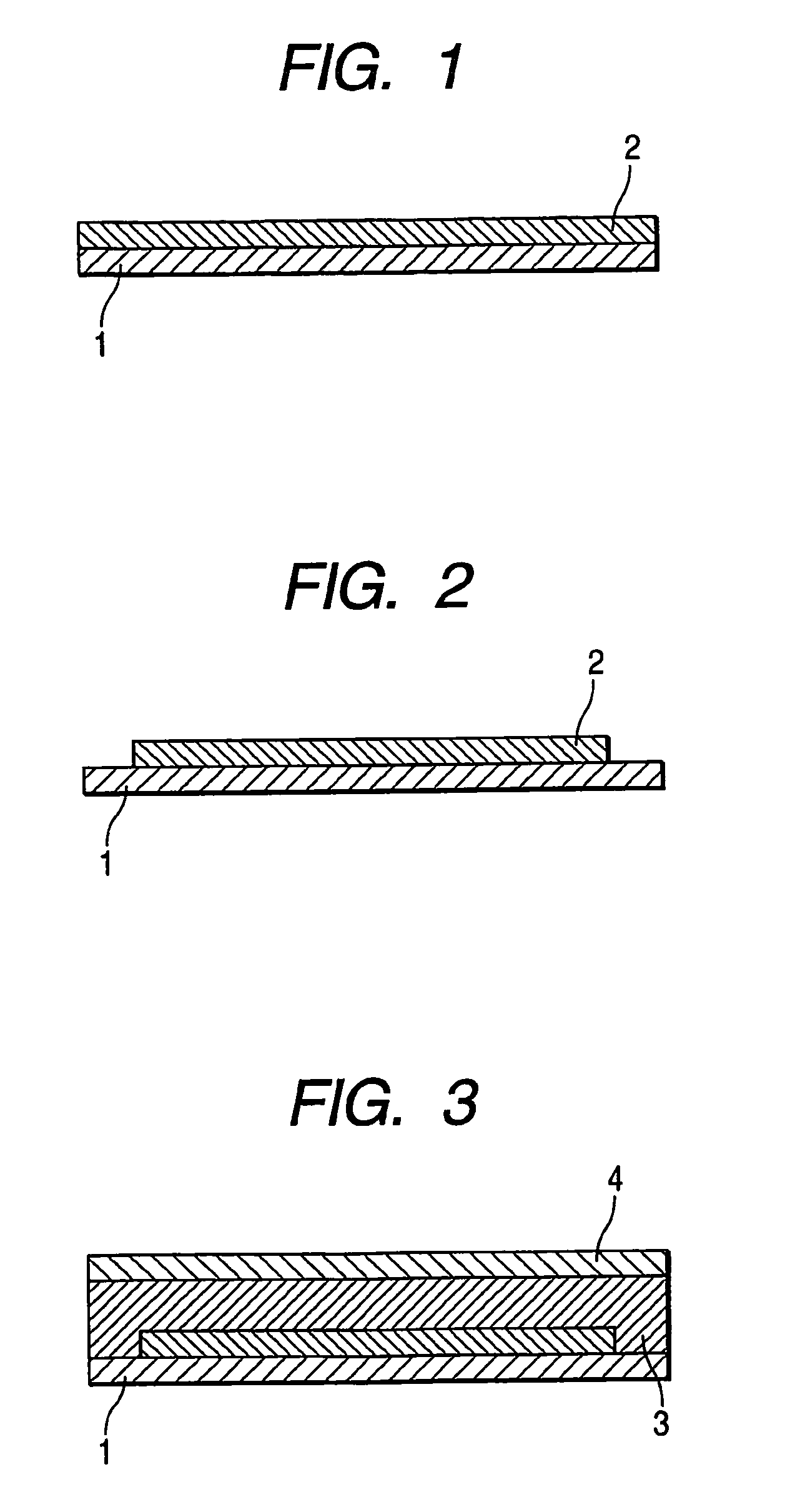
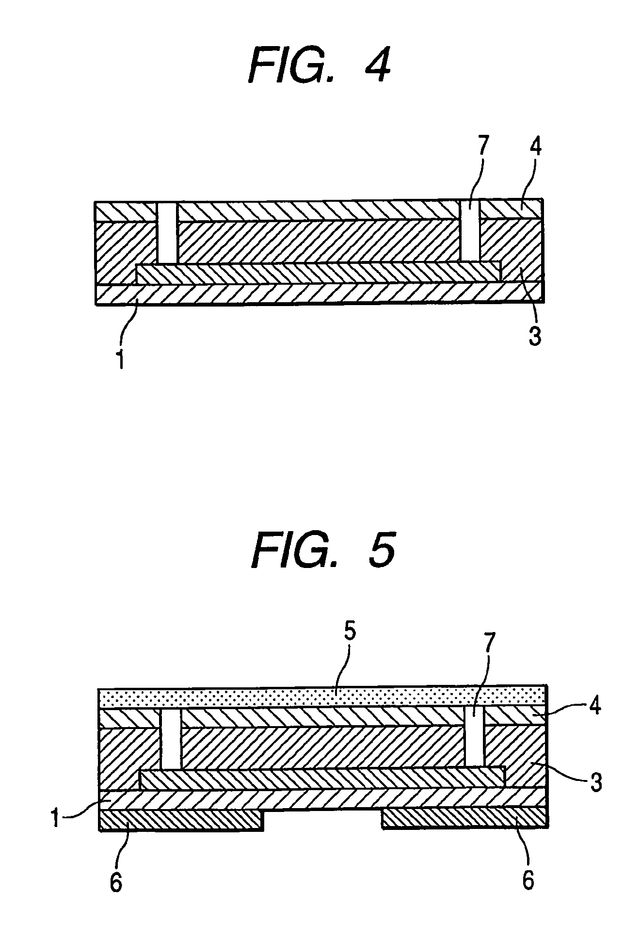
[0058]In Example 1, the ink jet head was manufactured by a method for manufacturing an ink jet head shown by FIGS. 1 to 7. First, the silicon substrate 1 in which the energy generating element for discharging the ink and the silicon substrate 1 on which a driver and a logic circuit were formed was prepared. Then, the positive type resist layer 2 including the photodegradable positive type resist was formed on the substrate 1 (FIG. 1). With reference to the photodegradable positive type resist, a resist solution, in which[0059]methyl methacrylate (MMA) / methacrylic acid (MAA) copolymer,[0060]MMA / MAA=90 / 10 (weight ratio), and[0061]weight average molecular weight=170000 (conversion of polystylene)

were dissolved in diethylene glycol dimethyl ether at a solid content concentration of 25 weight %, was applied by the spin coating method. The applied resist solution was pre-baked on a hot plate at a temperature of 100° C. for three minutes, and the pre-baking was further performed in a nitro...

example 2

[0089]The ink jet head was produced in the same manner as for Example 1 except that the resin shown below was used as the positive type resist layer 2:[0090]methyl methacrylate (MMA) / methacrylic acid (MAA) copolymer,[0091]MMA / MAA=90 / 10 (weight ratio), and[0092]weight average molecular weight=72000 (conversion of polystylene).

[0093]In the IR measurement similar to Example 1, the carboxyl group used for the intermolecular crosslinking was not more than 20%.

[0094]In the ink jet head produced by the above-described method, the crack and the dissolution and deformation of the positive type resist layer 2 were not observed. When the ink jet head produced by the above-described method was mounted on the printer to perform the discharge and recording evaluations, the stable printing could be realized and the high-quality printed matter was obtained.

example 3

[0095]The ink jet head was produced in the same manner as for Example 1 except that the resin shown below was used as the positive type resist layer 2:[0096]methyl methacrylate (MMA) / methacrylic acid (MAA) copolymer,[0097]MMA / MAA=90 / 10 (weight ratio), and[0098]weight average molecular weight=220000 (conversion of polystylene).

[0099]In the IR measurement similar to Example 1, the carboxyl group used for the intermolecular crosslinking was not more than 20%.

[0100]In the ink jet head produced by the above-described method, the crack and the dissolution and deformation of the positive type resist layer 2 were not observed. When the ink jet head produced by the above-described method was mounted on the printer to perform the discharge and recording evaluations, the stable printing could be realized and the high-quality printed matter was obtained.


PUM

PropertyMeasurementUnit
photosensitive wavelength rangeaaaaaaaaaa
thicknessaaaaaaaaaa

Abstract

A method of manufacturing an ink jet head, which includes a discharge port for discharging an ink droplet, an ink flow path communicated with the discharge port, and an energy generating element for discharging the ink droplet from the discharge port, includes providing a photodegradable resin layer on a substrate having the energy generating element, forming a structure which becomes the ink flow path by exposing and developing the photodegradable resin layer, coating the substrate having the structure which becomes the ink flow path with a negative type photosensitive resin layer, forming the ink discharge port in the negative type photosensitive resin layer, and forming the ink flow path communicated with the discharge port by removing the structure which becomes the ink flow path. The photodegradable resin layer includes a binary acrylic copolymer composition, which contains a unit obtained from (meta)acrylic ester as a main component and further contains a unit obtained from (meta)acrylic acid. The composition contains the (meta)acrylic acid unit at a proportion of 5 to 30 weight %, and a weight average molecular weight of the composition ranges from 50000 to 300000.

Description

TECHNICAL FIELD[0001]The present invention relates to a method for manufacturing an ink jet head and an ink jet head.BACKGROUND ART[0002]The ink jet head is applied to an ink jet recording method (liquid discharge recording method) in which the recording is performed by discharging a recording solution such as ink. The ink jet head generally includes an ink flow path, a liquid discharge energy generating portion provided in a part of the ink flow path, and a fine ink discharge port (also referred to as “orifice”) for discharging the ink in the ink flow path by energy of the liquid discharge energy generating portion. With reference to the conventional method of producing the ink jet head, for example, Japanese Patent Publication No. HO 6-045242 discloses a method for manufacturing an ink jet head (also referred to as cast molding method) in which a mold of the ink flow path is patterned onto the substrate, in which liquid discharge energy generating elements are formed, by a photose...

Claims


Application Information

Patent Timeline
Patent Type & Authority Patents(United States)
IPC IPC(8): B41J2/01B41J2/16
CPCB41J2/1603B41J2/1631B41J2/1639B41J2/1645B23K26/388B41J2/15B41J2/1404
Inventor OKANO, AKIHIKOSHIBA, SHOJIISHIKURA, HIROE
Owner CANON KK
Why Eureka
Try Eureka