Calculation system for inverse masks

a calculation system and mask technology, applied in the field of photolithography, can solve the problems of complex problems, inability to solve intrinsically simple problems, and easy pixel flipping in local minima, and achieve the effect of improving fidelity

Active Publication Date: 2009-02-03
SIEMENS PROD LIFECYCLE MANAGEMENT SOFTWARE INC
View PDF2 Cites 31 Cited by
  • Summary
  • Abstract
  • Description
  • Claims
  • Application Information

AI Technical Summary

Benefits of technology

[0006]To improve the fidelity by which a desired layout pattern can be printed on a wafer with a photolithographic imaging system, the present invention is a method and apparatus for calculating a mask or reticle layout pattern from a desired layout pattern. A computer system executes a sequence of instructions that cause the computer system to read all or a portion of a desired layout pattern and define a mask layout pattern as a number of pixel transmission characteristics. The computer system analyzes an objective function equation that relates the transmission characteristic of each pixel in the mask pattern to an image intensity on a wafer. The objective function also includes one or more penalty functions that enhance solutions meeting desired manufacturing restraints. Once the pixel transmission characteristics for the mask layout pattern are determined, the data can be provided to a mask writer to fashion one or more corresponding masks for use in printing the desired layout pattern.

Problems solved by technology

When partially coherent optics (4) is considered, the problem is complicated by the interactions mimj* between pixels and becomes a quadratic programming (QP) problem.
Reduction to LP is possible; however, the leanest relevant to microlithography and rigorous formulation must account for the partial coherence, so that the problem is intrinsically not simpler than QP.
The drawback is that pixel flipping can easily get stuck in the local minima, especially for PSM optimizations.
This however requires substantial simplifications.
Nashold projections belong to the class of the image restoration techniques, rather than to the image optimizations, meaning that the method might not find the solution (because it does not exists at all), or in the case when it does converge, we cannot state that this solution is the best possible.
Gerchberg-Saxton iterations tend to stagnate.
The convergence is slow because T is large, so that application to the large layout areas is problematic.
If we remove constraints, the problem becomes unbounded, with no minimum and no solutions.
If there is at least one dark and one bright pixel, the problem is indefinite.
This has important implications for the type of the applicable numerical methods: in large problems we can use factorizations of matrix Q, in huge problems factorizations are unrealistic.
The solutions of (55) increase image fidelity; however, the numerical experiments show that the contour fidelity of the images is not adequate.
The branch-and-bound global search techniques [18] are not the right choice because they are not well-suited for the large multi-dimensional optimization problems.

Method used


Image

  • Calculation system for inverse masks
  • Calculation system for inverse masks
  • Calculation system for inverse masks

Examples


Embodiment Construction

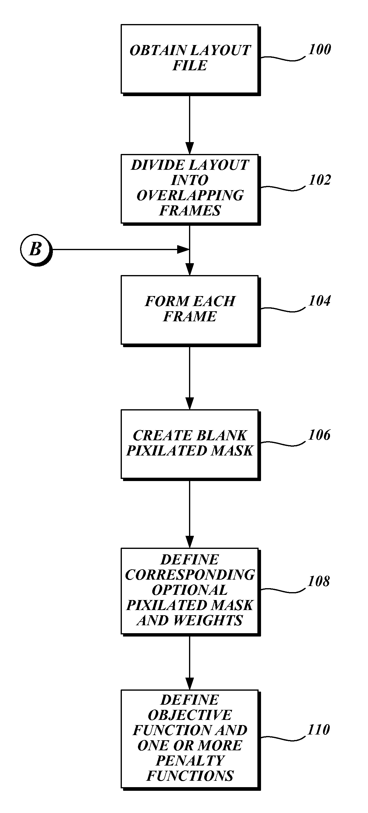
[0029]As will be explained in further detail below, the present invention is a method and apparatus for calculating a mask pattern that will print a desired layout or portion thereof on a wafer. FIG. 19 illustrates a representative computer system that can be used to calculate a mask layout pattern in accordance with one embodiment of the present invention. A computer system 50, including one or more programmable processors, receives a set of executable instructions on a computer-readable media 52 such as a CD, DVD, or from a communication link such as a wired or wireless communication network such as the Internet. The computer system 50 executes the instructions to read all or a portion of a desired layout file from a database 54 or other storage media. The computer system 50 then calculates data for a mask layout by dividing a mask layout into a number of discrete pixels. The computer system determines the transmission characteristic of each of the pixels so that the result on a w...


PUM


Abstract

A system for calculating mask data to create a desired layout pattern on a wafer reads all or a portion of a desired layout pattern. Mask data having pixels with transmission characteristics is defined along with corresponding optimal mask data pixel transmission characteristics. An objective function is defined having one or more penalty functions that promote solutions representing a desired resolution enhancement technique. Optimization of the objective function determines the transmission characteristics of the pixels in the mask data that is used to create one or more corresponding masks or reticles.

Description

CROSS-REFERENCE(S) TO RELATED APPLICATION(S)[0001]The present invention claims the benefit of U.S. Provisional Patent Application No. 60 / 657,260, filed Feb. 28, 2005; U.S. Provisional Patent Application No. 60 / 658,278, filed Mar. 2, 2005; and U.S. Provisional Patent Application No. 60 / 722,840, filed Sep. 30, 2005, which are all expressly incorporated by reference herein.FIELD OF THE INVENTION[0002]The present invention relates to photolithography, and in particular to methods of creating a semiconductor mask or reticle to print a desired layout pattern.BACKGROUND OF THE INVENTION[0003]With conventional photolithographic processing techniques, integrated circuits are created on a semiconductor wafer by exposing photosensitive materials on the wafer through a mask or reticle. The wafer is then chemically and mechanically processed to build up the integrated circuit or other device on a layer-by-layer basis.[0004]As the components of the integrated circuit or other device to be created...

Claims


Application Information

Patent Timeline
Patent Type & Authority Patents(United States)
IPC IPC(8): G06F17/50
CPCG03F1/144G03F1/36
Inventor GRANIK, YURI
Owner SIEMENS PROD LIFECYCLE MANAGEMENT SOFTWARE INC
Why Eureka
Try Eureka