
AC light emitting diode and AC LED drive methods and apparatus

a technology of led circuits and light emitting diodes, applied in the direction of basic electric elements, electric lighting sources, electric light sources, etc., to achieve the effects of reducing component size, simplifying the manufacturing and standardization of led circuits, and reducing or eliminating surge curren

Active Publication Date: 2009-02-10
LYNK LABS INC
View PDF9 Cites 271 Cited by
  • Summary
  • Abstract
  • Description
  • Claims
  • Application Information

AI Technical Summary

Benefits of technology

[0022]According to another aspect of the invention and LED circuit may be at least one pre-packaged LED and one pre-packaged diode connected together opposing parallel of each other, two opposing parallel pre-packaged LEDs, an opposing parallel LED string of pre-packaged LEDs or an opposing parallel LED matrix of pre-packaged LEDs having a capacitor in series of at least one junction of the connected LED circuits. The LED circuit capacitor allows for direct coupling of at least one LED circuit to the LED driver without additional series components such as capacitors and / or inductors between the LED circuit driver and the LED circuits. The LED circuit driver provides a relatively fixed voltage and relatively fixed frequency AC output even with changes to the load using feedback AC voltage regulator circuitry. The LED circuit's may be directly coupled and scaled in quantity to the LED circuit driver without affecting the other LED circuit's lumen output as long as the LED circuit driver maintains a relatively fixed voltage and relatively fixed frequency AC output.
[0039]With the LED circuit driver providing a known relatively constant AC voltage and frequency, mass production of various LED circuits with specific capacitor or RC network values would deliver 20 mA, 150 mA or 350 mA or any other desired current to the LED circuit based on the output of the specified LED circuit driver. The relatively fixed voltage and frequency allows for standardization of LED circuits through the standardization of LED circuit drivers.

Problems solved by technology

In some embodiments, LED circuits use a series resistor in addition to the capacitor providing an “RC” resistor capacitor network for certain LED circuit driver coupling that does not provide protection against surge currents to the LED circuits.

Method used


Image

  • AC light emitting diode and AC LED drive methods and apparatus
  • AC light emitting diode and AC LED drive methods and apparatus
  • AC light emitting diode and AC LED drive methods and apparatus

Examples


Embodiment Construction

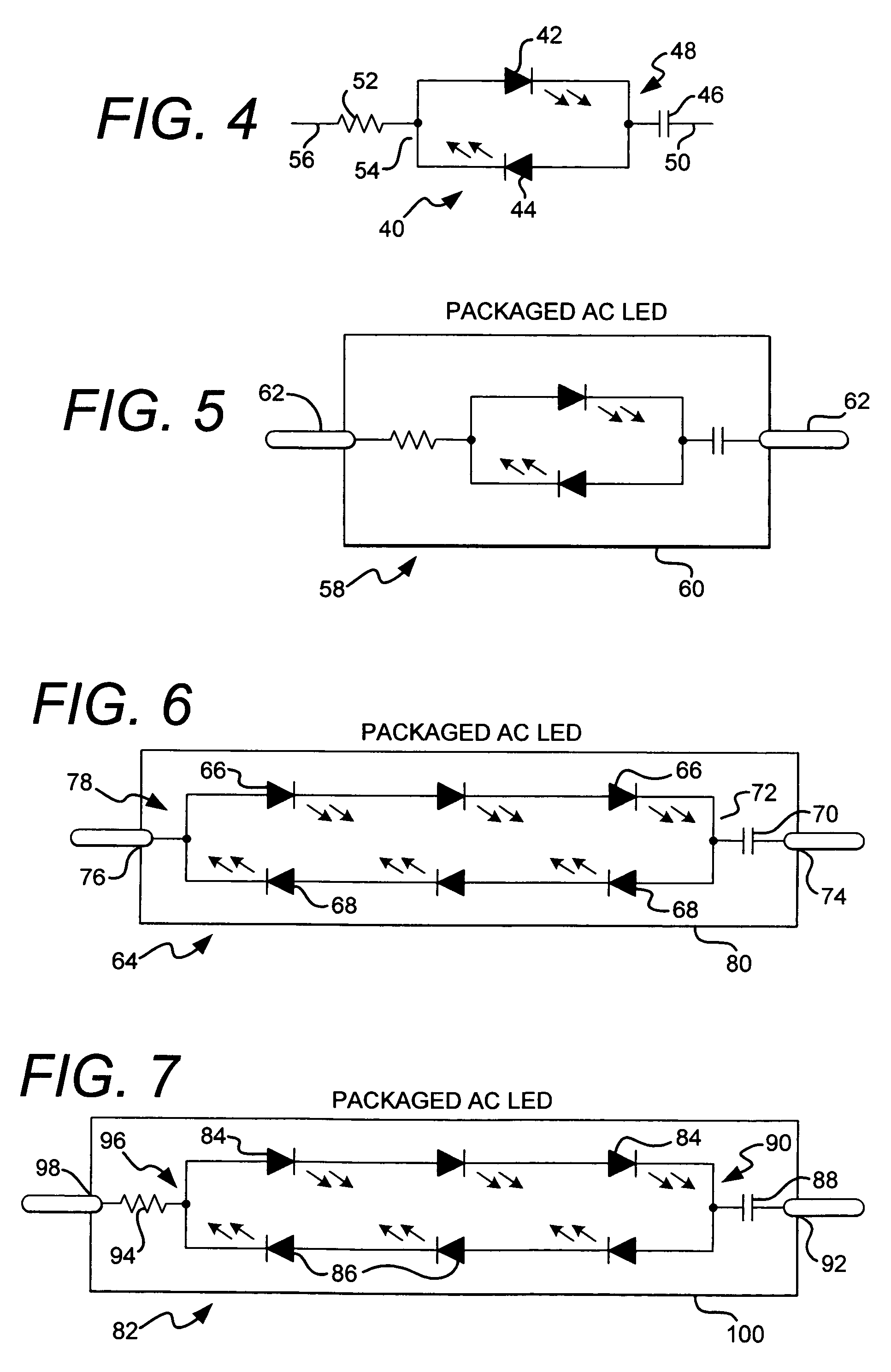
to Allen (hereinafter “Allen”) discloses AC powered LED-based light strings. Allen describes LED light strings employing series parallel blocks with a voltage matching requirement for direct AC drive placing fundamental restrictions on the number of diodes (LEDs) on each diode series block, depending on the types of diodes used. Allen discloses that for the forward voltage to be “matched,” in each series block, the peak input voltage must be less than or equal to the sum of the maximum forward voltages for each series block in order to prevent over-driving.

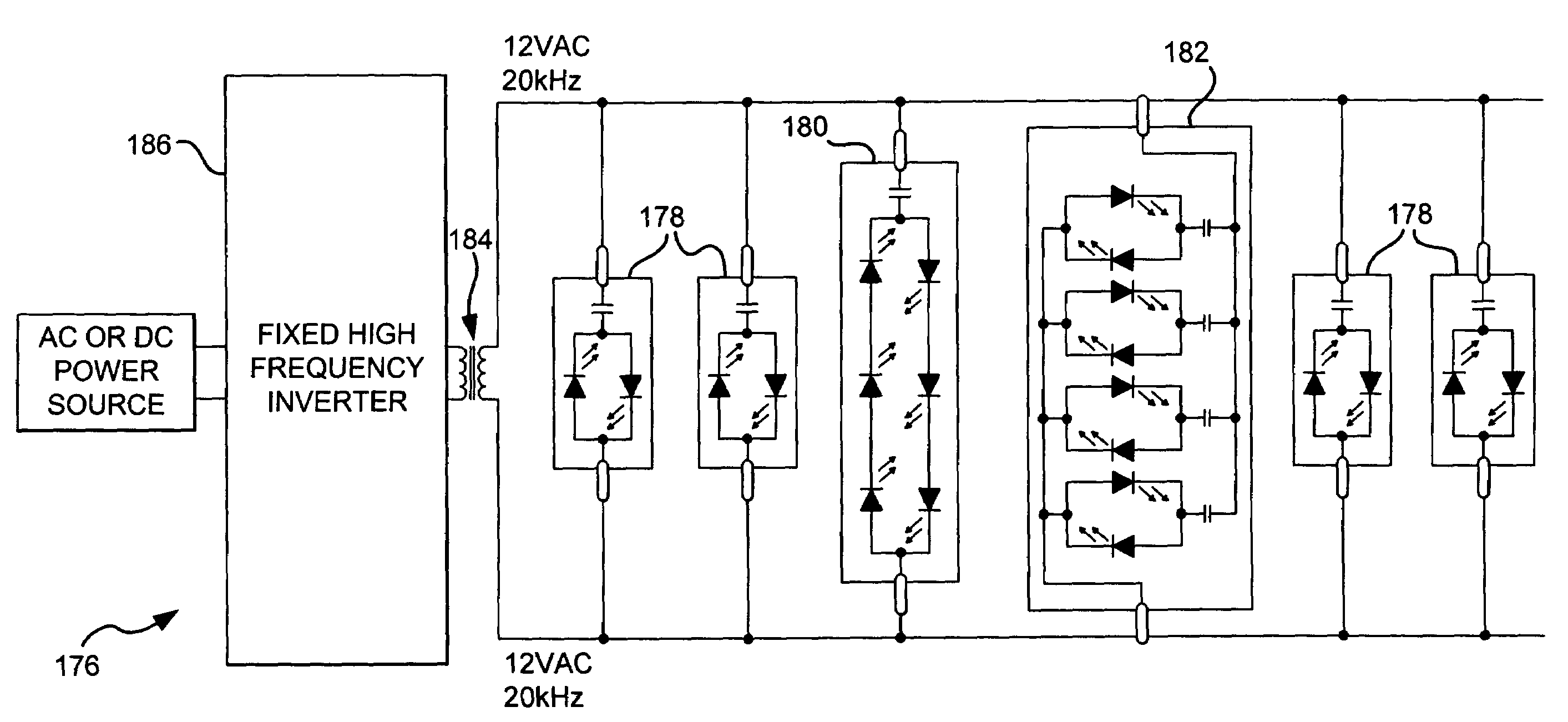
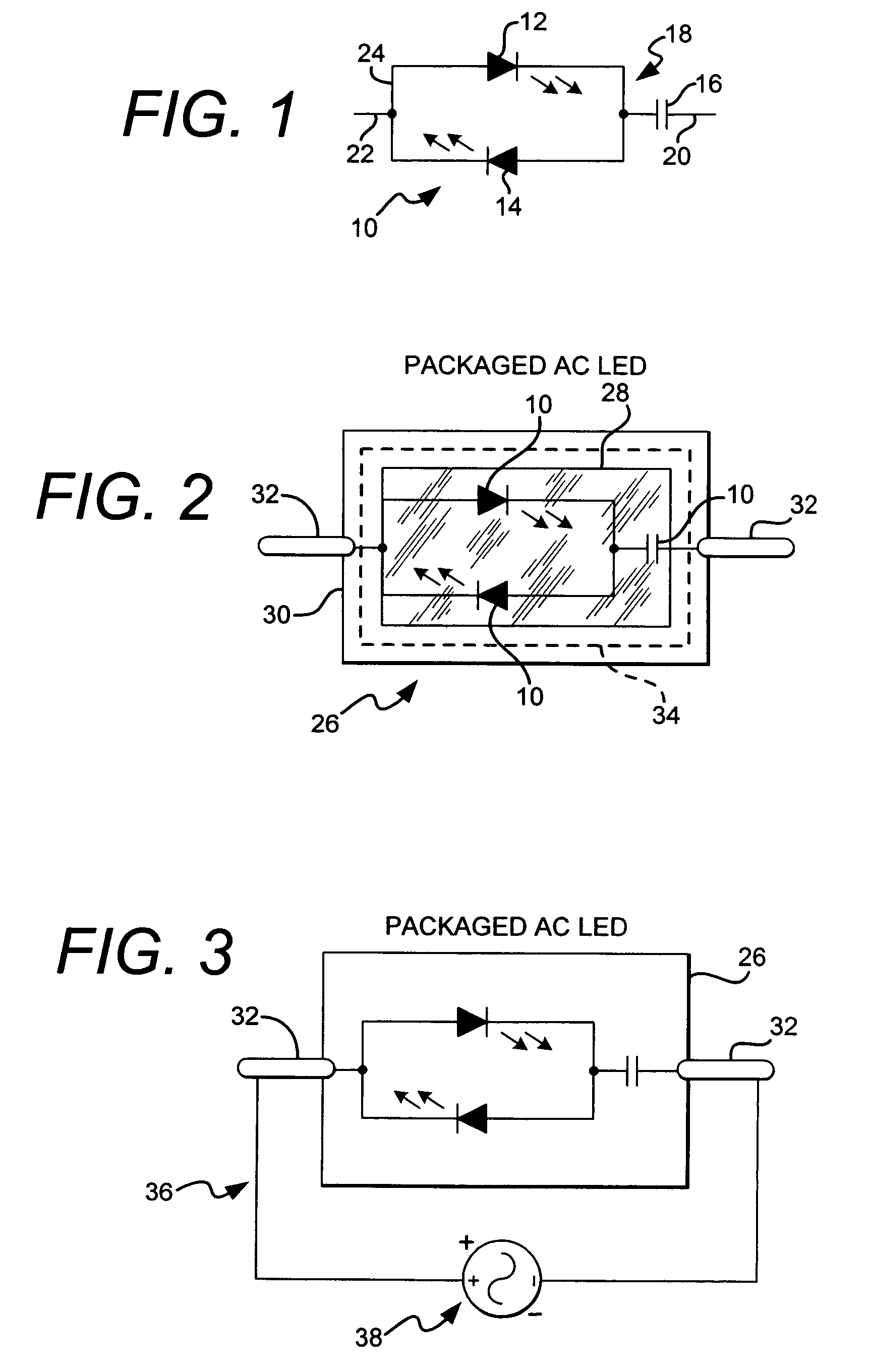
[0010]LEDs can be operated from an AC source more efficiently if they are connected in an “opposing parallel” configuration as shown by WO98 / 02020 and JP11 / 330561. More efficient LED lighting systems can be designed using high frequency AC drivers as shown by Patent Publication Number 20030122502 entitled Light Emitting Diode Driver (“Clauberg et. al.”) Clauberg et. al. discloses that higher frequency inverters may be used to driv...


PUM


Abstract

An AC LED package and circuits are disclosed along with an AC LED driver. The AC LED circuit may include as few as one LED or an array of anti-parallel LEDs driven with AC power sources and AC LED drivers at various voltages and frequencies. The AC LEDs are pre-packaged in various forms and materials and designed for mains or high frequency coupling in various forms to AC power sources, inverter type drivers or packages. The AC LED driver is a fixed frequency driver that provides a relatively constant voltage output to different size loads within the wattage limitation of the driver and in some cases is a direct mains power source.

Description

RELATED APPLICATIONS[0001]The present application claims priority to U.S. Provisional Application No. 60 / 547,653, filed Feb. 25, 2005 and U.S. Provisional Application No. 60 / 559,867, filed Apr. 6, 2004, both of which are incorporated herein by reference.TECHNICAL FIELD[0002]The present invention generally relates to light emitting diodes (“LEDs”) and LED drivers. The present invention specifically relates to alternating current (“AC”) driven LEDs, LED circuits and AC drive circuits and methods.FEDERALLY SPONSORED RESEARCH OR DEVELOPMENT[0003]None.BACKGROUND OF THE INVENTION[0004]1. Field of the Invention[0005]The present invention generally relates to light emitting diodes (“LEDs”) and LED drivers. The present invention specifically relates to alternating current (“AC”) driven LEDs, LED circuits and AC drive circuits and methods.[0006]2. Description of the Related Art[0007]LEDs are semiconductor devices that produce light when a current is supplied to them. LEDs are intrinsically DC...

Claims


Application Information

Patent Timeline
Patent Type & Authority Patents(United States)
IPC IPC(8): H05B37/00H05B44/00
CPCH05B33/0818H05B33/0821H01L2924/0002H01L2924/00H05B45/382H05B45/39H05B45/42
Inventor MISKIN, MICHAELANDERSEN, JAMES N.
Owner LYNK LABS INC
Learn More