Piston for a rotary combustion engine

a technology of rotary combustion engine and piston, which is applied in the direction of rotary piston engine, rotary or oscillating piston engine, engine lubrication, etc., can solve the problems of high cost, time-consuming, and difficult production of conventional piston housings, and achieve the effect of streamlined process for producing pistons

Inactive Publication Date: 2009-02-17
WANKEL SUPER TEC
View PDF10 Cites 0 Cited by
  • Summary
  • Abstract
  • Description
  • Claims
  • Application Information

AI Technical Summary

Benefits of technology

[0009]To produce this unit, it is proposed that a circumferential weld be produced by electron-beam welding under vacuum, proceeding radially from the outside in the planes of the flat surfaces, while the sidewalls are resting against the piston housing. To produce a satisfactory weld, it is necessary to clamp the parts in question together with an appropriate device, so that their prepared flat surfaces rest flush against each other, because welding produces the best results when applied to solid pieces of material with the smallest possible gaps between them. It has been found that the process for producing the piston can be streamlined even more by lining up and clamping together in the axial direction a plurality of the elements to be welded together, namely, a plurality of sidewalls, of takeoff-sidewalls, and of piston housings, so that the vacuum generated for the welding process can be used for as many welding passes as possible. Each time the workpieces are changed, a new vacuum must be generated, which is expensive and time-consuming.
[0010]The thickness of the one sidewall and that of the takeoff-side sidewall in the region where they are welded should be greater than the depth of one of the arc strip grooves and / or sealing pin bores in order to prevent the combustion pressure from escaping into the interior of the piston through gaps which might be produced when the recesses for the sealing elements are machined.
[0012]To eliminate the steps required to produce the arc strip grooves during the final phase of piston production, the outer circumferential contours of the sidewalls are laid against the outer flanks of the arc strip grooves which, in the region of the sealing pins, extend transversely to the pin surface, the primary goal here being to minimize the size of the gaps. After the base of the groove and the inner flank of the arc strip groove have been milled into the external contour of the sidewall, there is no need for any further machining to produce the arc strip grooves.
[0016]The object of the invention is therefore to create a piston for a rotary combustion engine which can be manufactured at lower cost by means of a new production method but which does not make it necessary to make any process-related changes or functional compromises affecting the interior in the region of the oil profiles and / or ribs, and which is at least equivalent in strength or even superior to the conventional piston.

Problems solved by technology

The conventional housing is much more difficult to manufacture, however, because the sidewalls make it necessary to use a casting mold of complicated design.
Each time the workpieces are changed, a new vacuum must be generated, which is expensive and time-consuming.

Method used


Image

  • Piston for a rotary combustion engine
  • Piston for a rotary combustion engine
  • Piston for a rotary combustion engine

Examples


first embodiment

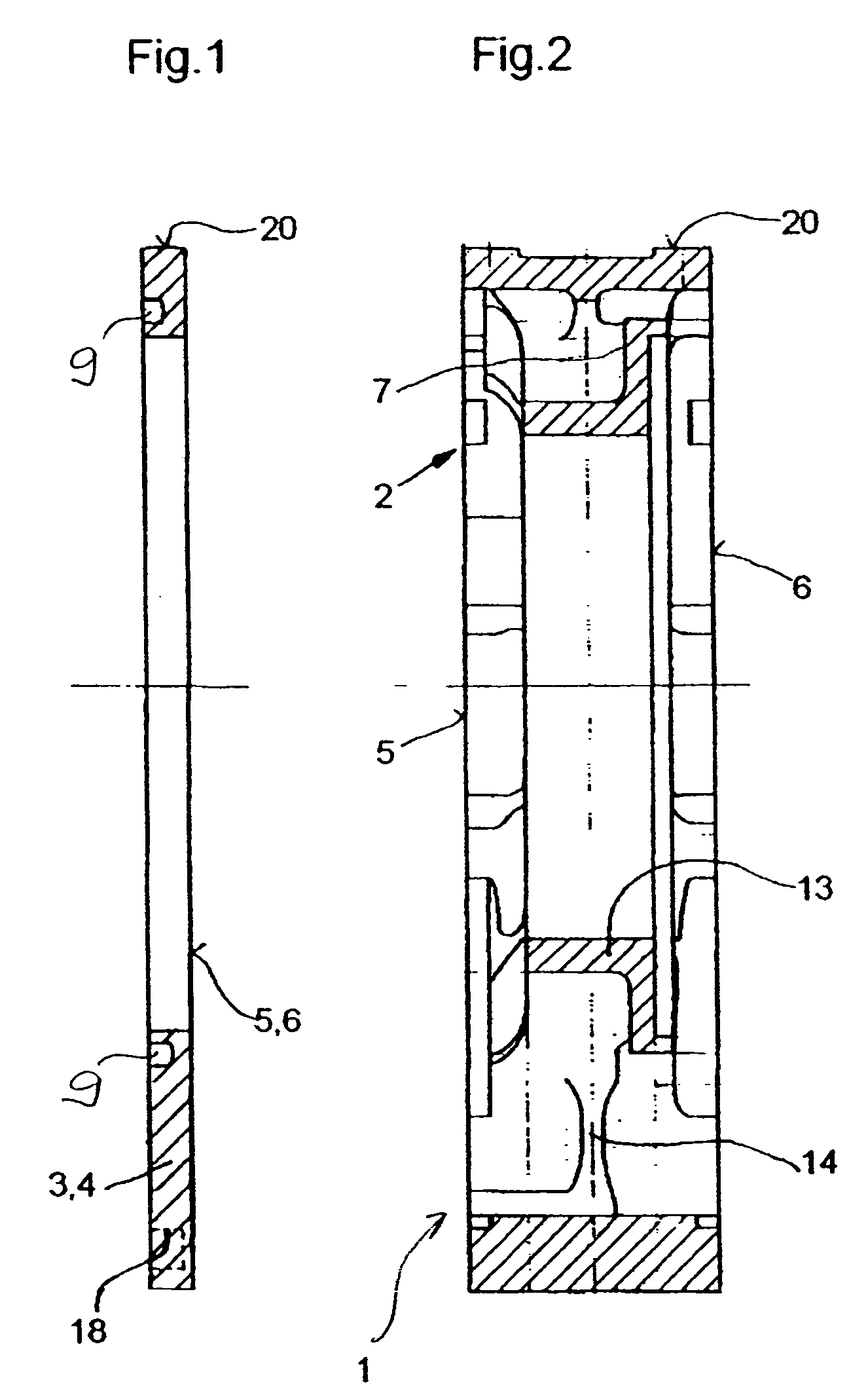
[0031]FIG. 2 shows a piston housing 2, which has a flat surface 5 on one side and a flat surface 6 on the power takeoff side, against which the sidewalls 3, 4 are placed and clamped. The piston contour 20 extends around the outer circumference. When the sidewalls 3, 4 are clamped together with the housing, the outside contours of all three parts must be brought into alignment. A ring element 13 is coaxial to the center line of the piston 1. The ring serves as a support for the piston 1 on the eccentric shaft 52 (FIG. 10) and is made as an integral part to the piston housing 2, being connected to it by a plurality of ribs 14. A weld 8 can be seen in the enlarged view of FIG. 5; this weld allows the material in the region of the flat surfaces 5, 6 to run together and thus produces the piston 1 as a single unit. Arc strip grooves 9 and the sealing pin bores 18 can now be machined into the sidewalls 3, 4 in the conventional manner.

second embodiment

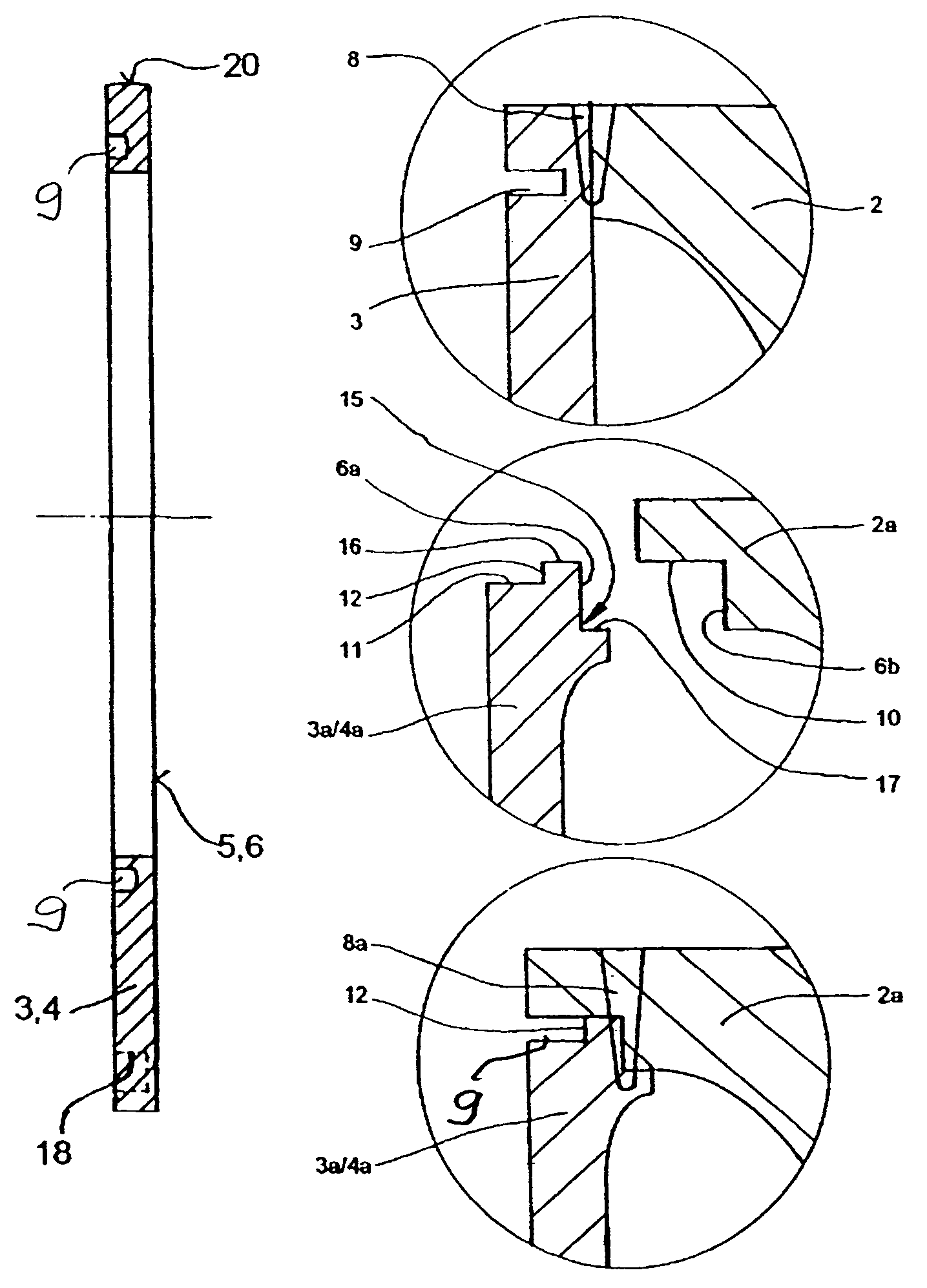
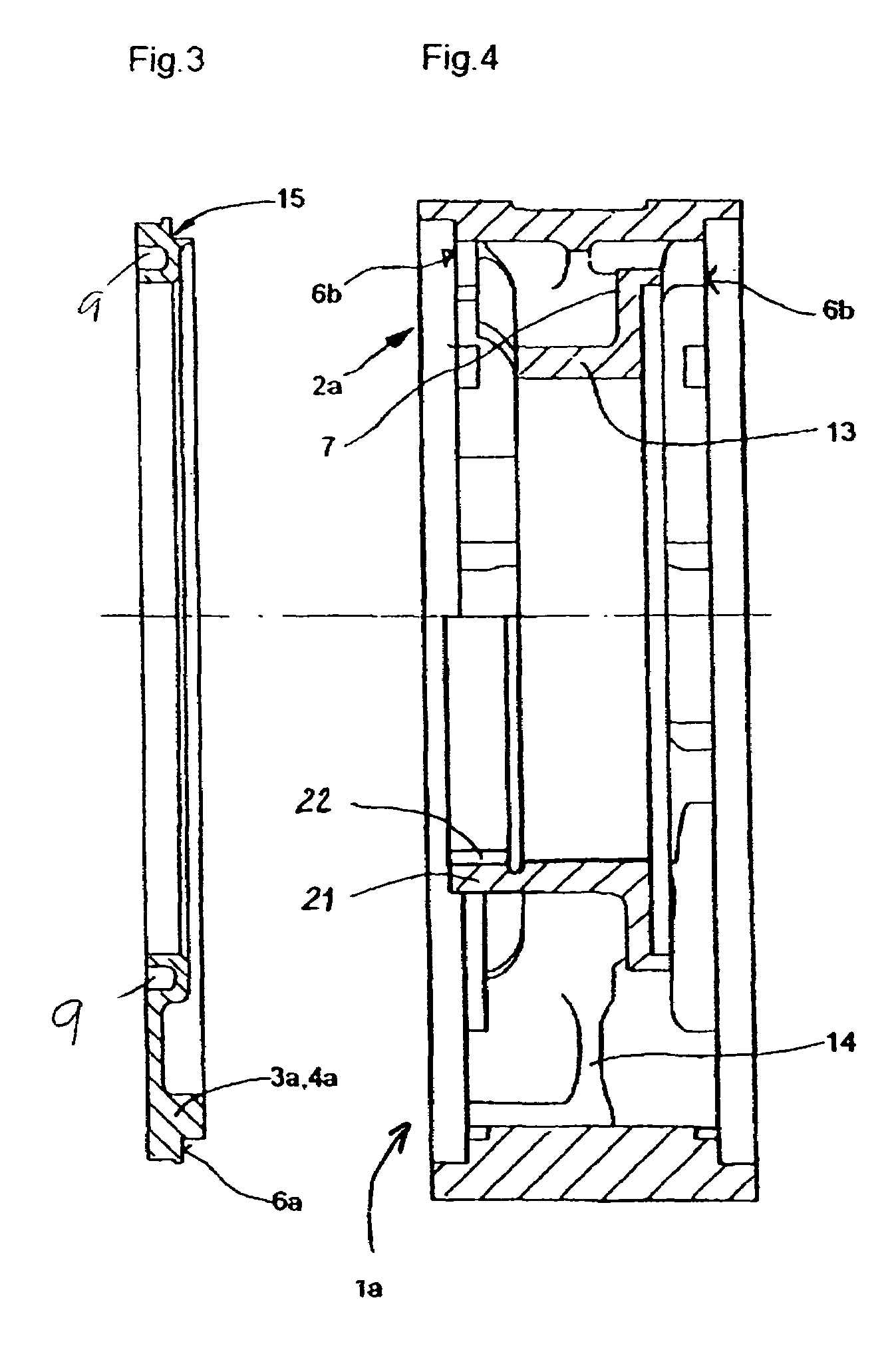
[0032]For a piston la, FIG. 3 shows a sidewall 3a, which is identical in design to a sidewall 4a on the power takeoff side. Each of the sidewalls 3a, 4a has a circumferential contact surface 6a, which can be laid against a circumferential contact surface 6b of the piston housing 2a, as can be seen in FIG. 4. Here, a ring-shaped shoulder 21 with the outside dimensions of an internal gear 22 is formed integrally on the ring element 13. It is obvious from a simultaneous consideration of the enlarged views of FIGS. 6 and 7 that the sidewall 3a, 4a is bounded externally by a first contour 16, which coincides with an outer flank 10 of the arc strip groove 9 in the piston housing 2a. The previously mentioned circumferential contact surface 6a is bounded by a second contour 17, so that a right-angled step 15 is formed, which is equidistant from the first contour 16. The sidewall 3a can now be installed in the previously described position on the piston housing 2a.

[0033]For the sake of effic...

third embodiment

[0034]a piston 1b can be seen in the enlarged views of FIGS. 8 and 9. This piston has a housing 2b, which is similar to a conventional piston except for a ring element 13a, which must be welded into the piston housing 2b. In this embodiment, the interior of the piston housing 2b with its oil-conducting profiles is no longer open on both sides; instead, it is open radially toward the inside, which makes the work of the model builder easier to the extent that a circumferential core can be used for casting, which costs less to produce than the cores used for the production of the conventional piston, the number of which must be the same as the number of ribs 14. A weld 8b connects each rib 14 to the ring element 13a in the region of an encircling cylindrical plane 19.

[0035]In comparison with first embodiment, second embodiment offers the advantages of optimal welds 8a, of a simple method for connecting the sidewalls 3a, 4a, and of the elimination of the need for machining the arc strip...


PUM


Abstract

A rotary combustion engine with at least one working unit, which has essentially a peripheral engine housing, a side housing plate on one side, a side housing plate on the power takeoff side, a triangular piston, and an eccentric shaft. The piston is configured of several parts, which are connected to each other. The connection is accomplished by electron-beam welding under vacuum, which yields excellent results as long as certain conditions are met. The one sidewall and the power takeoff sidewall of the piston are preferably welded to a piston housing, as a result of which the casting molds can be of simpler design and simpler contours can be used, which leads to welds of higher quality and to a decrease in the costs of casting.

Description

BACKGROUND OF THE INVENTION[0001]1. Field of the Invention[0002]The invention pertains to a rotary piston engine.[0003]2. Description of the Related Art[0004]A piston for a rotary combustion engine is known from German Patent No. DE 37 28 943 C2 (U.S. Pat. Ser. No. 4,971,533). This piston rotates around an epitrochoidal orbit between the side housing plates and has sealing strips at the three tips by which it always remains in contact with the epitrochoidal orbit, where the piston is divided in a radial plane into two parts, and where means are provided so that these two parts can be pressed by their webs, which form the radially outer edges of the piston flanks, against the side housing plates, and so that an elastically deformable ring-shaped seal can be installed to seal off the gap between the two parts radially from the inside. These means consist of three guide pins, which are mounted with freedom to slide back and forth in sets of aligned bores with parallel axes passing thro...

Claims


Application Information

Patent Timeline
Patent Type & Authority Patents(United States)
IPC IPC(8): F01C1/02F01C19/08F01C21/00F01C21/08F02B53/00F02B53/10F01C1/08F01C1/22F04B17/00F04B35/00
CPCF01C1/084F01C1/22F02B2053/005F02B2730/018
Inventor BAIER, WOLFGANGEIERMANN, DANKWART
Owner WANKEL SUPER TEC
Why Eureka
Try Eureka