
Mathematical model for predicting the thermal behavior of an item

Inactive Publication Date: 2009-02-17
THE UNITED STATES OF AMERICA AS REPRESENTED BY THE SECRETARY OF THE NAVY
View PDF8 Cites 8 Cited by
  • Summary
  • Abstract
  • Description
  • Claims
  • Application Information

AI Technical Summary

Benefits of technology

[0014]Yet another object of the present invention is to provide a thermal behavior modeling method that does not require copious amounts of item-specific data such as size, shape, and weight.
[0016]It is another object of the present invention to provide a thermal behavior modeling method that is sufficiently flexible (mathematically) for use in a variety of thermal response applications.
[0018]Yet another object of the present invention is to provide a thermal behavior modeling method that does not require the use of proprietary software.

Problems solved by technology

However, when the object in question has a large thermal mass and a complicated internal configuration with different materials, the thermal response of the inside parts lags the skin response and the mathematical equations describing the thermal response are not easy to develop.
While the rise of computer technology has aided the process significantly, the creation of the initial model has always been a very cumbersome process requiring a great deal of time.
Unfortunately, the Aderhold et al. technique / system only generates a series of temperature correction values, it does not provide a thermal behavior model (i.e. each temperature correction value is used as an offset to actual temperature measurements obtained from a series of temperature sensors).
Unfortunately, significant re-programming effort and knowledge would be required to modify / customize a generic software application, such as that identified above, for use in thermal behavior modeling.
Even then, the modified / customized application would not readily provide the user-friendly visual controls required to manually approximate non-linear regression by manipulating a set of generic curves to fit a set of actual measured curves.

Method used


Image

  • Mathematical model for predicting the thermal behavior of an item
  • Mathematical model for predicting the thermal behavior of an item
  • Mathematical model for predicting the thermal behavior of an item

Examples


Embodiment Construction

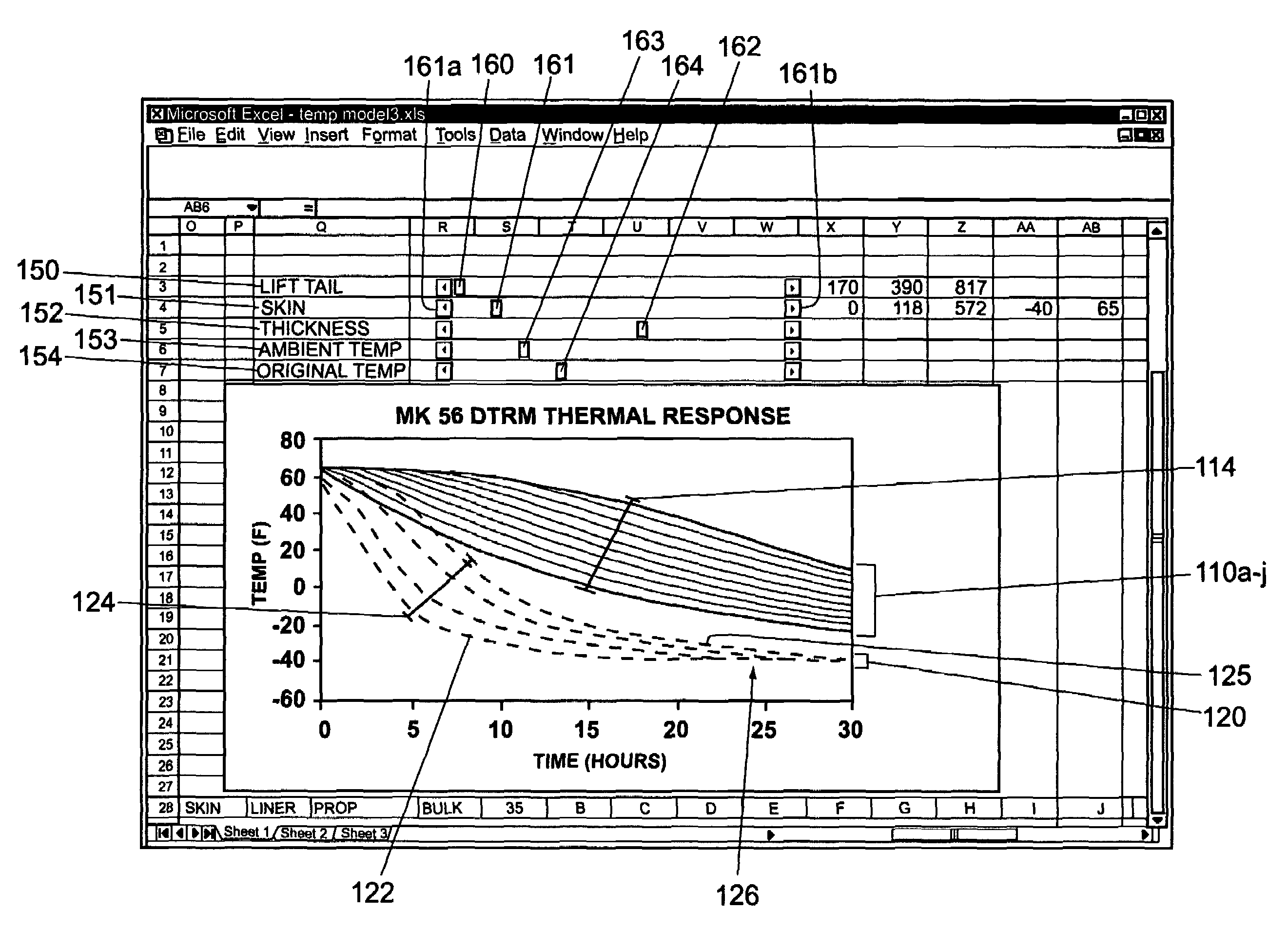
[0035]The present invention is a method for mathematical modeling of the thermal behavior of an item subjected to conditions meant to induce heat transfer within the item. The method is readily implemented in software form for use on a conventional computer workstation with an appropriate operating system and spreadsheet application. The computer workstation may be, for example, a conventional personal computer with standard internal components (e.g. a microprocessor with peripheral chipset mounted on an appropriate motherboard). Of course, other more or less powerful computer systems can be used, but it is suggested that the computer system meet the minimum system requirements for Microsoft® Excel®, or an equivalent spreadsheet software application. The user interface is preferably a conventional color monitor and standard input devices such as a keyboard and mouse. The operating system is preferably Microsoft® Windows 98®, or a later revision. The software of the present invention...


PUM


Abstract

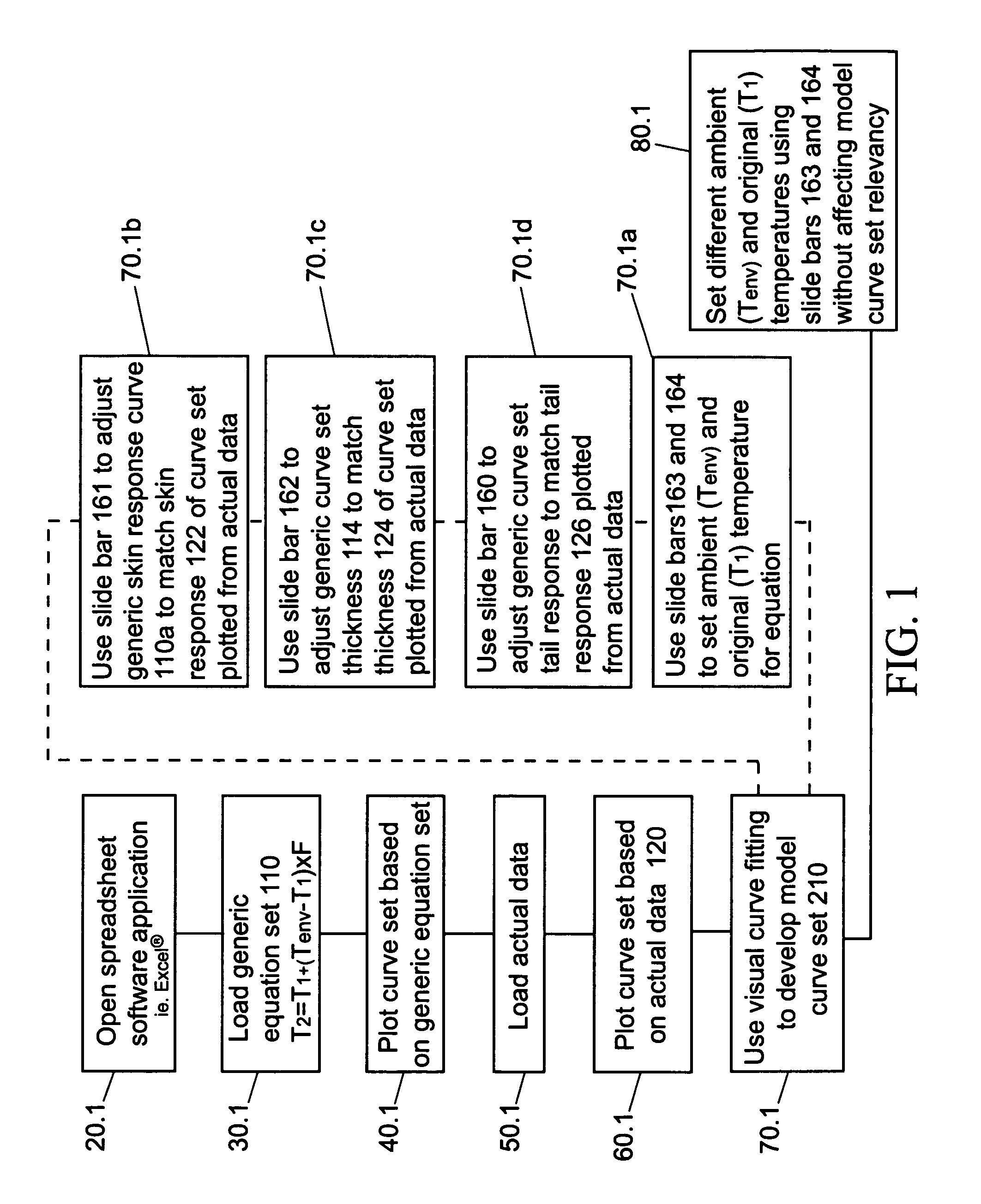
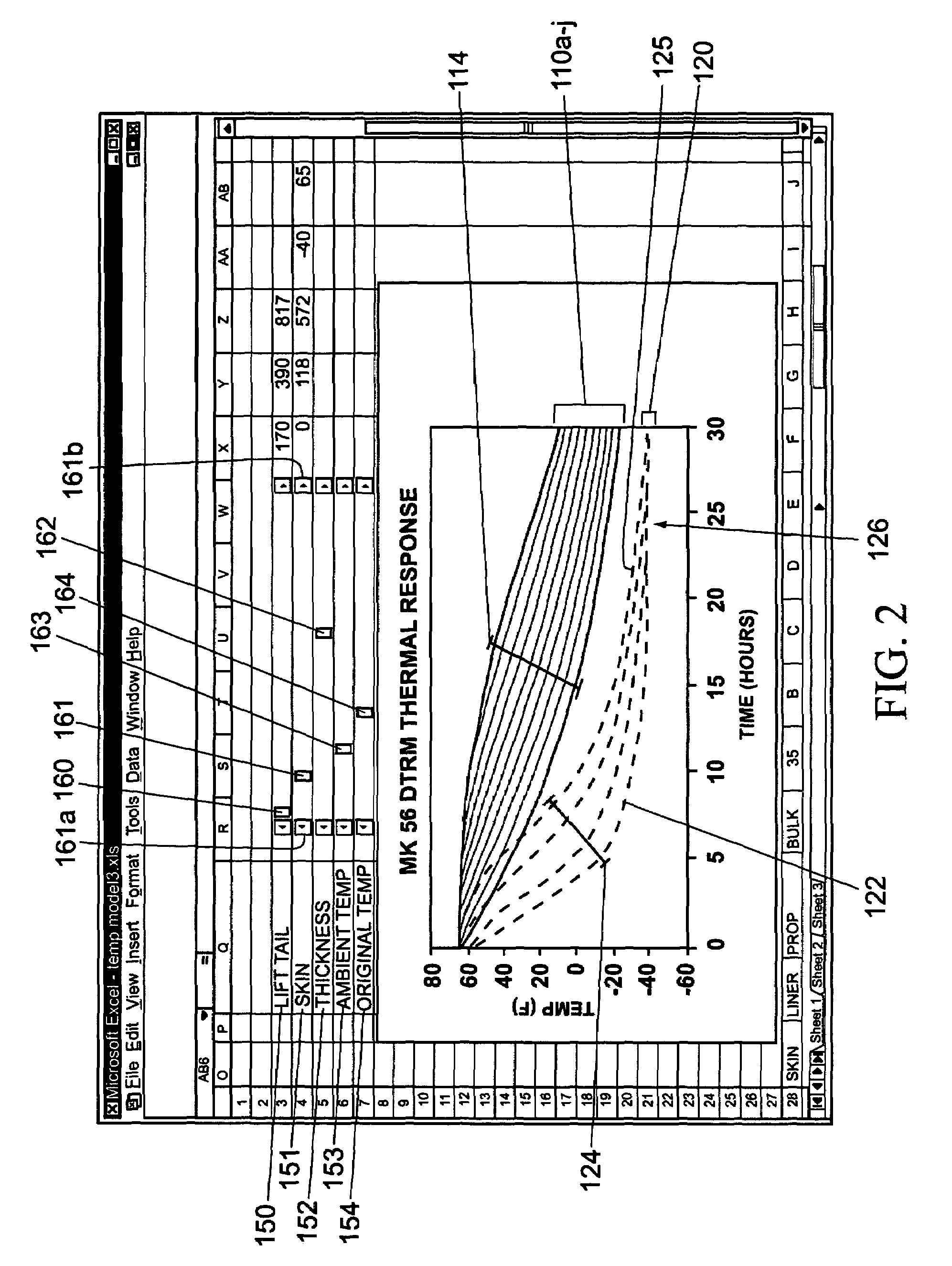
A visual curve fitting method for mathematically modeling the thermal response of an item based upon the generic thermal response equation T2=T1+(Tenv.−T1)×F. Using a spreadsheet application with a graphical user interface (GUI), a graph is displayed with a set of generic thermal response curves and a set of actual thermal response data curves. By manipulating a series of slide bars displayed on the GUI, values are selected and input into the generic equation in order to change the shape and position of the generic curve set. Manipulating the slide bars in combination until the generic curve set overlays the actual curve set results in a set of equations (thermal model) that accurately characterizes the thermal behavior of the item under a reasonable range of temperature changes.

Description

STATEMENT OF GOVERNMENT INTEREST[0001]The invention described herein may be manufactured and used by or for the government of the United States of America for governmental purposes without the payment of any royalties thereon or therefor.BACKGROUND OF THE INVENTION[0002]1. Field of the Invention[0003]The present invention relates to mathematical modeling techniques and, more particularly, the process of visually fitting one or more curves to a limited set of empirical data for the interpolation or extrapolation of a complete predictive data set and, even more particularly, to a simplified means for describing and predicting the thermal behavior of an item subjected to conditions meant to induce heat transfer within the item.[0004]2. Description of the Background[0005]The basic concept of a thermal model works through mathematical manipulation of equations with the purpose of matching a predetermined thermal response. Conventional thermal models are based upon the fact that an object...

Claims


Application Information

Patent Timeline
IPC IPC(8): G06F17/10
CPCG06F17/5009G06F2217/80G06F30/20G06F2119/08
Inventor GARCIA, ARIEL F.
Owner THE UNITED STATES OF AMERICA AS REPRESENTED BY THE SECRETARY OF THE NAVY
Learn More