Arrangement and method for controlling and regulating bottom hole pressure when drilling deepwater offshore wells

a deepwater offshore well and pressure regulation technology, applied in the direction of drilling pipes, drilling well accessories, sealing/packing, etc., can solve the problems of increasing the dynamic force of the bottom hole, increasing the pressure of the bottom hole than is required for formation control, and increasing the difficulty of drilling. the effect of the operator

Inactive Publication Date: 2009-03-03
ENHANCED DRILLING
View PDF34 Cites 93 Cited by
  • Summary
  • Abstract
  • Description
  • Claims
  • Application Information

AI Technical Summary

Benefits of technology

[0031]In another aspect the invention gives a particular benefit in well controlled situations (kick handling) or for planned drilling of wells with hydrostatic pressure from drilling fluid less that the formation pressure. This can involve continuous production of hydrocarbons from the underground formations that will be circulated to the surface with the drilling fluid. With this novel invention, both kick and handling of hydrocarbon gas can be safely and effectively controlled.
[0062]Since the drilling riser can be disconnected from a closed subsea BOP, it can be safer to drill under-balanced than from other installations that does not have this combination. The reason also is that the gas pressure in the riser is very low and will cause the drill string to be “pipe heavy” at all times, excluding the need for snubbing equipment or “pipe light” inverted slips in the drilling operation. If pressure build up in the gas / air phase cannot be kept low, a reduction in the riser pressure can be achieved by closing the subsea BOP and taking the return through the equalizing loop, thereby reducing the pressure in the riser. This stems from the fact that the friction pressure from fluid flowing in the reduced diameter of the equalizing loop will increase the bottom hole pressure, hence a reduced pressure in the drilling riser will be achieved.

Problems solved by technology

Particularly for smaller diameter hole sizes these additional dynamic forces become significant.
As the drilling fluid must have a specific gravity such that the fluid remaining in the well is still heavy enough to control the formation when the drilling marine riser is disconnected, this creates a problem when drilling in deep waters.
This is due to the fact that the marine riser will be full of heavy mud when connected to the sub sea blowout preventer, causing a higher bottom-hole pressure than required for formation control.
This results in the need to set frequent casings in the upper part of the hole since the formation cannot support the higher mudweight from the surface.
This also means that slimhole or slender wells are difficult to construct with present methods in deeper waters.
This gives rise to several grave problems if having to handle hydrocarbons and in kick and well control handling.
This prior art can not be used for under-balanced purposes where the drilling riser is used for gas separation, since the prior art does not have a surface pressure containment system that can be used for gas pressure containment.
Nor does it incorporate the particular benefit achieved by not having the need for the kill and choke lines and the high pressure riser bypass in well control situations.
These two above-mentioned examples of prior art, however, does not incorporate a method to adjust and compensate for the ECD effect.
Normally it is not possible to control the pressure from the surface in a conventional drilling operation, due to the fact that the well returns will flow into an open flow line at atmospheric pressure.
However, this is a time consuming process and requires adding chemicals and weighting materials to the drilling mud.
Higher circulating rates generates higher friction pressure and consequently higher pressures in the bore hole.
The disadvantage of using frictional pressure control is that control is lost when drilling fluid circulation is stopped.
Frictional pressure loss is also limited by the maximum pump rate, the pressure rating of the pump and by the maximum flow through the down hole assembly.

Method used


Image

  • Arrangement and method for controlling and regulating bottom hole pressure when drilling deepwater offshore wells
  • Arrangement and method for controlling and regulating bottom hole pressure when drilling deepwater offshore wells
  • Arrangement and method for controlling and regulating bottom hole pressure when drilling deepwater offshore wells

Examples


Embodiment Construction

[0072]Other and numerous embodiments of the invention are within the scope of the appended claims. What follows is illustrative of the invention but not limiting of the scope of the claims. In the following detailed description, taken in conjunction with the foregoing drawings, equivalent parts are given the same reference numerals.

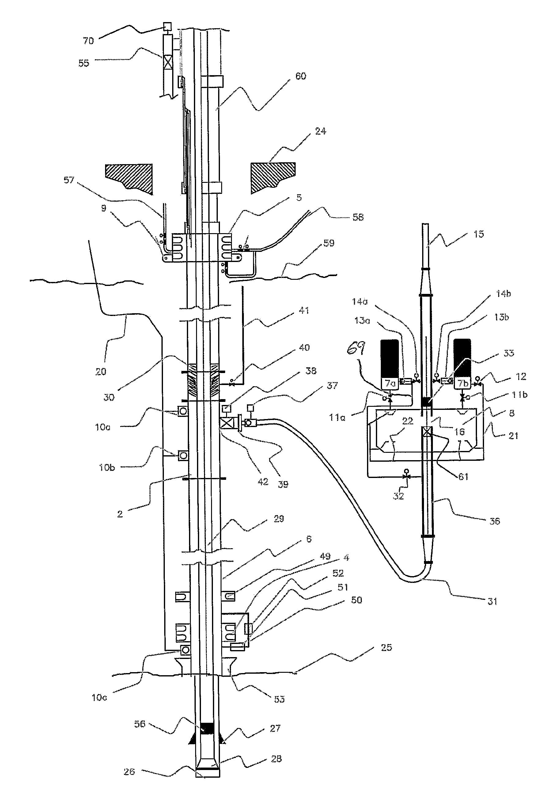
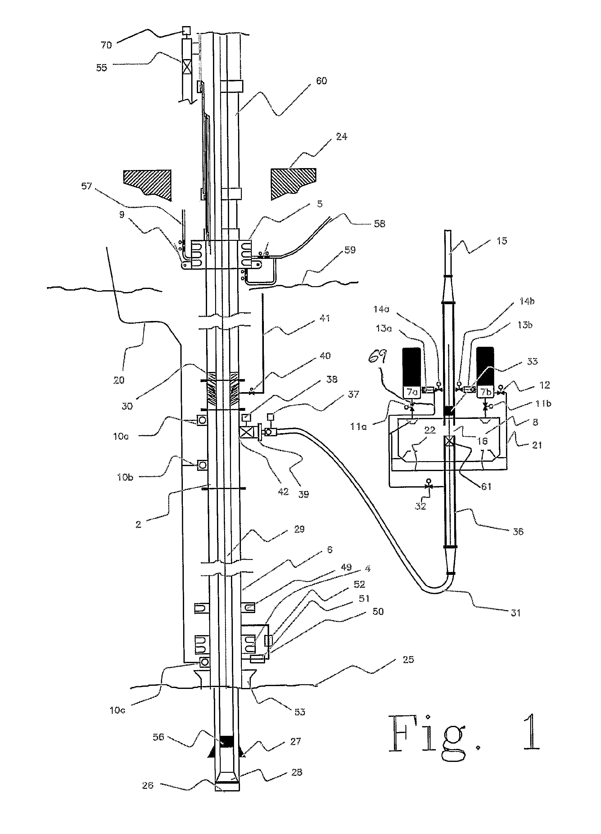
[0073]FIG. 1 illustrates a drilling platform 24. The drilling platform 24 can be a floating mobile drilling unit or an anchored or fixed installation. Between the sea floor 25 and the drilling platform 24 is a high-pressure riser 6 extending, a subsea blowout preventer 4 is placed at the lower end of the riser 6 at the seabed 25, and a surface blowout preventer 5 is connected to the upper end of the high pressure riser 6 above or close to sealevel 59. The surface BOP has surface kill and choke line 58, 57, which is connected to the high pressure choke-manifold on the drilling rig (not shown). The riser 6, does not require outside kill and choke lines exte...


PUM


Abstract

An arrangement and method for controlling and regulating bottom hole pressure in a well during subsea drilling in deep water involves adjustment of a liquid / gas interface level in a high pressure drilling riser up or down to change the slope and offset of the pressure gradient in the well. The arrangement may include a surface BOP and gas bleeding outlet at the upper end of the drilling riser, a lower BOP with a by-pass line, and an outlet at a depth below the water surface that is connected to a pumping system with a flow return conduit running back to a drilling vessel or platform.

Description

RELATED APPLICATIONS[0001]This application is a continuation of pending U.S. application Ser. No. 10 / 489,236, filed Mar. 10, 2004, which is a U.S. National Phase Application of PCT Application No. PCT / NO02 / 00317, filed Sep. 10, 2002, which claims the benefit of U.S. Provisional Application No. 60 / 318,391, filed Sep. 10, 2001. Each of these applications is herein incorporated in its entirety by reference.FIELD OF THE INVENTION[0002]The present invention relates to a particular arrangement for use when drilling oil and gas wells from offshore structures that float on the surface of the water in depths typically greater than 500 m above seabed. More particularly, it describes a drilling riser system so arranged that the pressure in the bottom of an underwater borehole can be controlled in a completely novel way, and that the hydrocarbon pressure from the drilled formation can be handled in an equally new and safe fashion in the riser system itself.BACKGROUND OF THE INVENTION[0003]This ...

Claims


Application Information

Patent Timeline
Patent Type & Authority Patents(United States)
IPC IPC(8): E21B7/12E21B21/00E21B21/01E21B21/08E21B21/10E21B34/08
CPCE21B21/001E21B21/01E21B21/08E21B21/10E21B2021/006E21B21/085E21B7/128E21B33/035E21B17/01
Inventor FOSSLI, BORRE
Owner ENHANCED DRILLING
Why Eureka
Try Eureka