Although this procedure is well perfected the patient suffers intense pain and a long
recovery.
When performing anastomosis during such
surgery on a
beating heart, use of hand-suturing to attach the graft vessel is very imprecise due to the translation of movement from the
beating heart to the suspended
artery.
Any imprecise placement of the sutures may cause a
distortion of the anastomosis which may cause
stenosis at this junction.
To accomplish this feat of precision on a moving target is extremely difficult.
To make matters worse, the site is often bloody due to the fact that the heart has not been stopped.
During
beating heart surgery, the surgeon can attempt to minimize the deleterious effects of the beating
heart motion by using suspension or retraction techniques, but it is impossible to isolate all such movement (and attempts to minimize the motion can damage the vessel being restrained or cause myocardial injury).
Even when performing anastomosis in an ‘open chest’ surgical setting in which the surgeon has adequate access and vision of the
surgical site to manipulate the
anatomy and instruments, it is difficult to perform the hand-suturing required in traditional methods.
When performing anastomosis in a minimally
invasive procedure access to (and vision of) the site is more limited and the hand-suturing is more difficult.
If the sutures are not placed correctly in the vessel walls, bunching or leaks will occur.
During a minimally
invasive procedure this is disastrous, usually resulting in the conversion to an open chest procedure to correct the mistake.
Any rough handling of the vessel walls is detrimental as
inflammation can cause further postoperative complications.
Although minimally invasive CABG procedures are taking place now with hand-sutured anastomosis they require superlative
surgical skills and are therefore not widely practiced.
However, the prior art techniques often require the vessels to be severely deformed during the procedure.
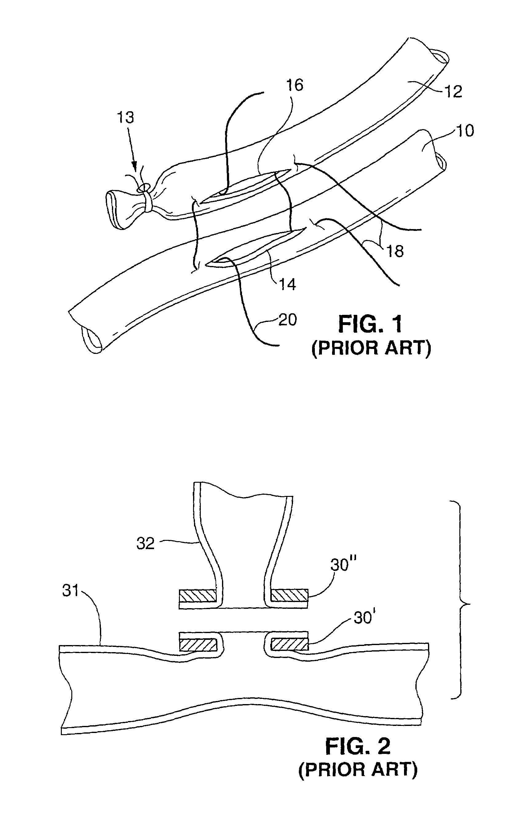
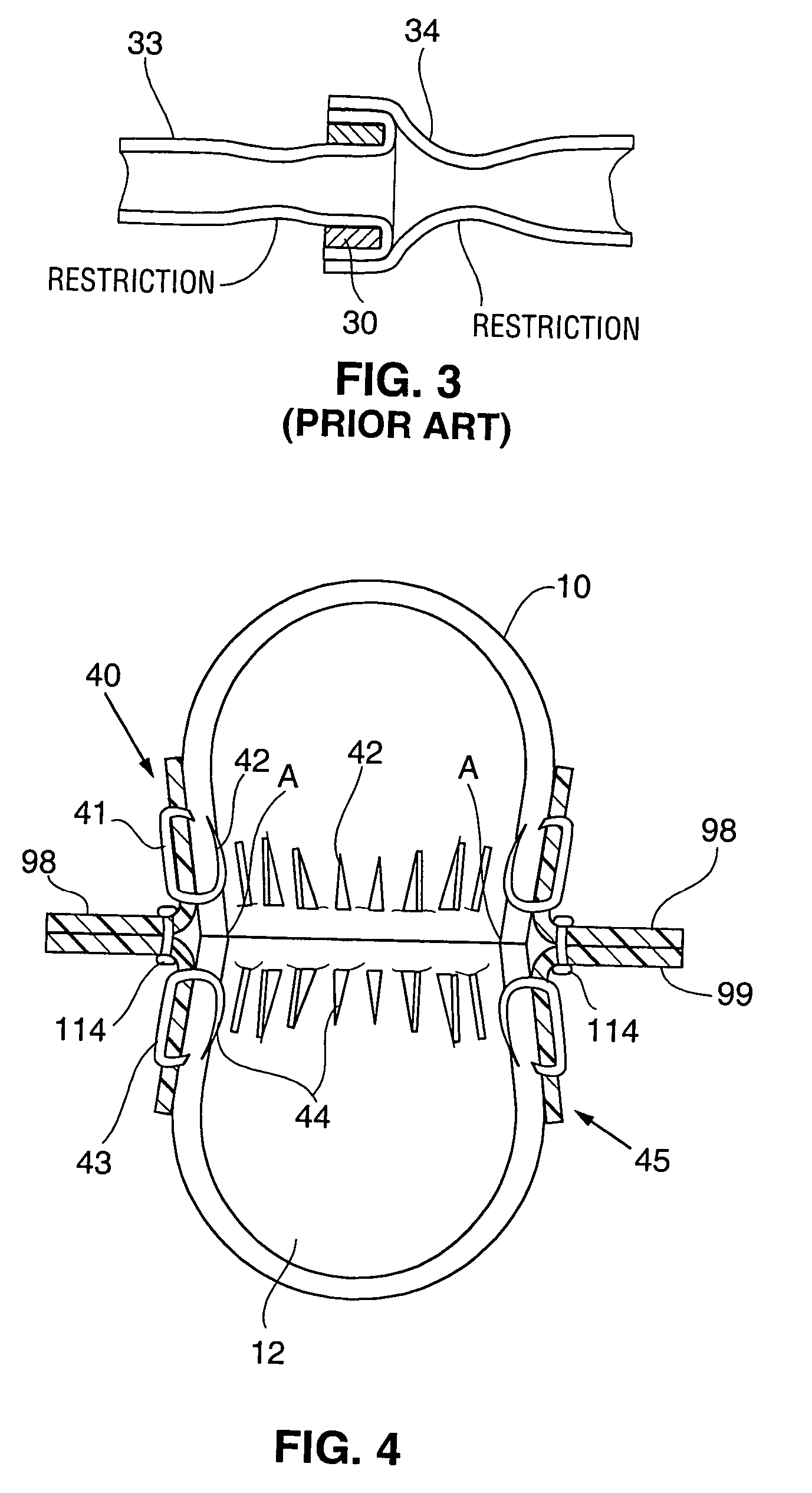
However, it may be undesirable to simply slit side-wall tissue of a vessel and pull the incised edges through a ring (as in FIG. 2) to anchor them on a
flange (or to invert and pull tissue at the end of a vessel over a ring as in FIG. 3).
Pulling or stretching the vessel walls can produce an unpleasant and unexpected result.
Therefore, the tissue will not stretch as easily in the radial or circumferential direction and results in a narrowing or restriction when pulled or stretched in the prior art devices.
Such manhandling will result in restrictions and stenotic junctions because the vessel walls will react poorly to being treated in such a rough manner and the stretching of the vessel wall will telegraph up the vessel wall due to the high radial stiffness of the
vessel structure, causing restrictions and spasms in the vessel wall.
Additionally, prior art methods and apparatus for anastomosis without hand-suturing do not adequately ensure
hemostasis to avoid leakage from the anastomosis junction under pressure, and they attempt to accomplish
hemostasis through excessive clamping forces between clamping surfaces or stretching over over-sized fittings.
If the edges are tied too loosely, the wound will leak and have trouble healing causing excessive
scar tissue to form.
If the edges are tied too tightly, the sutures will tear through the delicate tissue at the suture hole causing leaks.
Conventional junctions that include rings are anatomically incorrect both for
blood flow and for healing.
The prior art junctions do not account for such flow characteristics and parameters and are thus deficient.
With a rigid ring that is a singular circular cross section of the graft, the fitting does not allow the vessel to provide this increase in flow as the vessels expand to meet the needs of the heart
muscle.
If the incised edges are too far apart scarring will occur causing restrictions.
The walls cannot be compressed tightly between two hard surfaces which will damage the vessels.
However, clamping and compressing the vessel walls too tightly will cause
necrosis of the vessel between the clamps.
If
necrosis occurs the dead tissue will become weak and most likely cause a failure of the joint.
Still further Such rings and tubes used to clamp vessels together do not follow the correct anatomical contours to create an unrestricted anastomosis.
Failing to account for the way healing of this type of junction occurs, and not accounting for the actual situation may cause a poor result.
In a mechanical minimally invasive
system it will not be possible to put in an ‘extra suture throw’ so the
system must provide a way to assure complete
hemostasis.
If the design errs on the side of not over-compressing the tissue, there may be very small areas that may present a leak between the edges of the vessel walls.
Healing with prior art techniques using mechanical joining means is not as efficient as it could be.
This saves time and resources and may be necessary if only short sections or a limited amount of host graft material is available.
Conventional means and methods of performing an anastomosis do not permit the formation of multiple anastomotic sites on a single graft vessel such as at both proximal and distal ends.
This will be either impossible or very expensive.
As noted above, performing anastomosis in a minimally invasive manner while the patient's heart is beating requires an extremely high degree of dexterity.
However, the cuffs are designed (and attached to the vessels) such that when the two cuffs are aligned, the incised tissue edges of the two vessels are placed in edge-to-edge contact (so that there is a risk that the anastomosis will be completed without the intima of the two vessels being in direct contact with each other at all locations where the vessels meet each other).
However, the
cuff is designed (and attached to the first vessel) such that when the
cuff is aligned with the second vessel, the incised tissue edges of the two vessels are placed in edge-to-edge contact (so that there is a risk that the anastomosis will be completed without achieving direct intima-to-intima contact at all locations where the vessels meet each other).
Since the intima tissue provides
lubricity and a
low friction surface against which blood can flow, failure to accomplish uniform intima-to-intima contact between the two vessels has several disadvantages, including the following: blood flowing from one joined vessel to the other may encounter a “gap” in the intima layer to which it is exposed (a hole in an otherwise continuous intima layer at which intima tissue is missing) so that the blood comes into direct contact with the tissue that is normally shielded from the blood by intima tissue.
If this occurs, the flowing blood can create a
false lumen by separating tissue
layers of one or both of the vessels, or the flowing blood can otherwise cause damage at the anastomosis site which hinders healing or results in leakage.

