
Rapid prototyping apparatus

a technology of rapid prototyping and production apparatus, which is applied in the direction of program control, process and machine control, butter production, etc., can solve the problems of insufficient self-supporting of construction layers comprising only bm printed cross sections of construction objects, total or partial blockage of output orifices, and inaccuracy in deposition of construction materials, etc., to achieve the effect of improving structural strength

Active Publication Date: 2009-03-10
OBJET GEOMETRIES
View PDF16 Cites 324 Cited by
  • Summary
  • Abstract
  • Description
  • Claims
  • Application Information

AI Technical Summary

Benefits of technology

"The invention is about an improved inkjet printing apparatus that can produce objects with better quality and efficiency. It has several features such as a shuttle with dismountable and replaceable printing heads, a support surface, and a controller that controls the shuttle and printing heads. The printing heads have alignment structures that allow for accurate positioning when replacing them. The apparatus also has an improved lamp for curing photopolymer construction materials and a cleaning wiper for removing excess material. The invention provides an improved method for producing objects by sequentially forming layers of construction material on a support surface."

Problems solved by technology

For many construction objects, because of the complexity and / or shape of the objects, construction layers comprising only BM printed in the shape of cross sections of the construction objects are not completely self-supporting and require support during construction of the object.
The accumulated material may result in total or partial blockage of output orifices, generating inaccuracies in deposition of construction material and / or damage to a printed layer as the printing heads and roller move over a printed layer.
Often, functioning of a printing head block may be so degraded by accumulated photopolymer “debris” that the printing block must be replaced.
Replacing a printing head block is generally expensive, time consuming, and requires recalibration of the RPA so that deposition of polymer via the output orifices can be accurately controlled.

Method used


Image

  • Rapid prototyping apparatus
  • Rapid prototyping apparatus
  • Rapid prototyping apparatus

Examples


Embodiment Construction

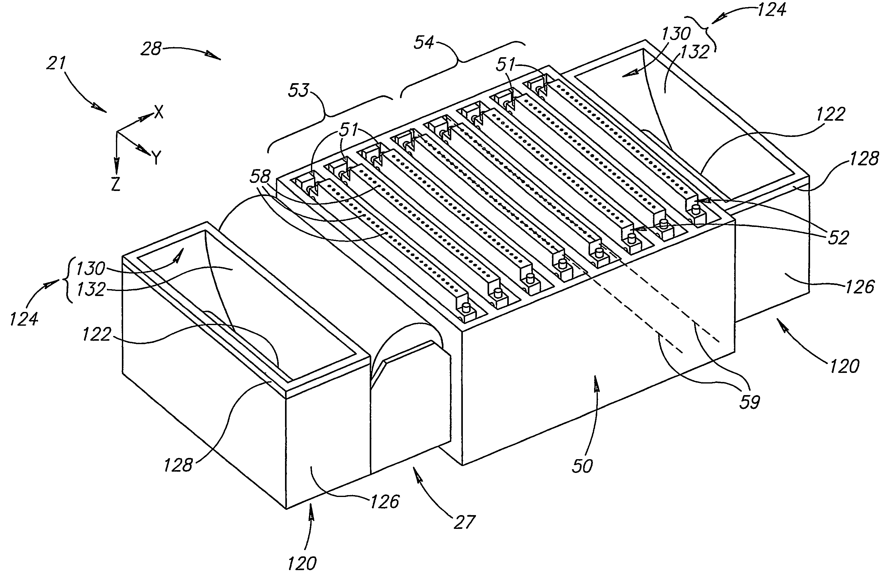
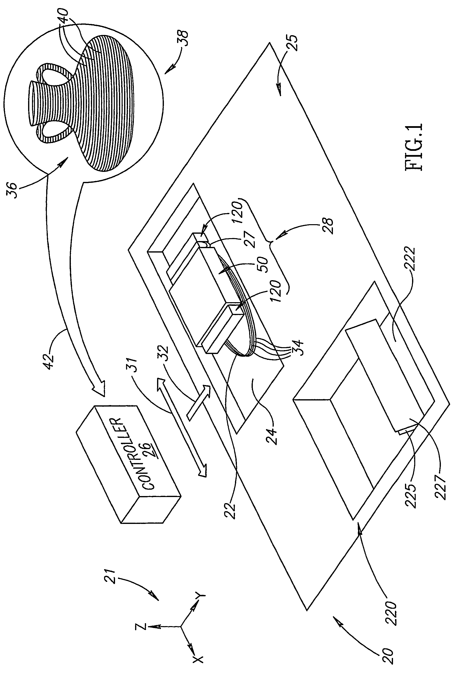
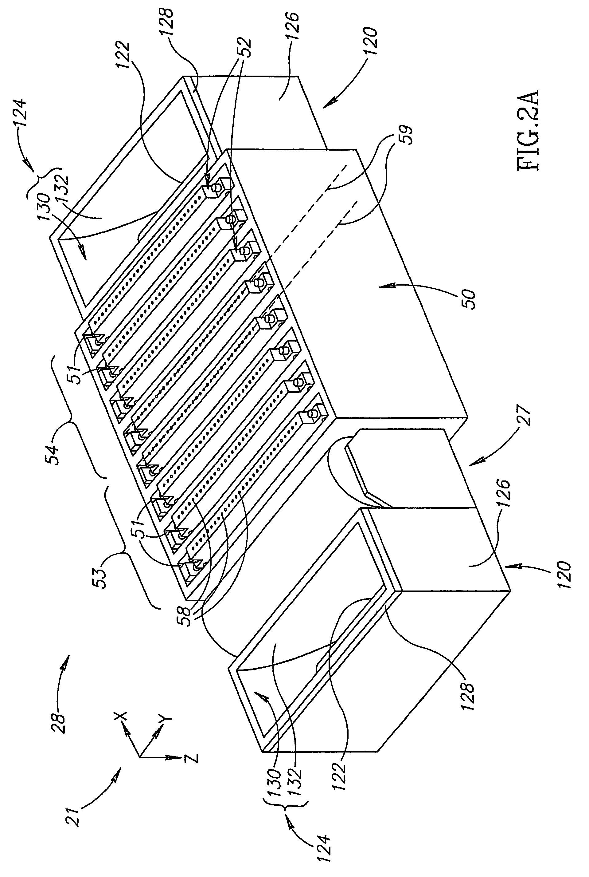
[0089]FIG. 1 schematically shows an ink-jet RPA 20 producing an object 22 on a construction platform 24, in accordance with an embodiment of the present invention. RPA 20 comprises a controller 26 and a shuttle 28 comprising a printing head block 50, a leveling roller 27 and, optionally, two sources 120 of radiation suitable for polymerizing photopolymers used by the RPA to construct objects, in accordance with an embodiment of the invention. Optionally, construction platform 24 is mounted to a worktable 25 and is controllable to be lowered and raised with respect to the worktable.

[0090]Periodically, during production of object 22, RPA 20 controller 26 moves shuttle 28 to a maintenance area 220 on worktable 25 comprising a sump 222 and at least one cleaning blade. By way of example, maintenance area 220 comprises two cleaning blades, a first cleaning blade 225 and a second cleaning blade 227. At maintenance area 220 controller 26 performs a cleaning procedure to remove waste constru...


PUM

PropertyMeasurementUnit
angleaaaaaaaaaa
angleaaaaaaaaaa
angleaaaaaaaaaa

Abstract

Apparatus for producing an object by sequentially forming thin layers of a construction material one on top of the other responsive to data defining the object, the apparatus comprising: a plurality of printing heads each having a surface formed with a plurality of output orifices and controllable to dispense the construction material through each orifice independently of the other orifices; a shuttle to which the printing heads are mounted; a support surface; and a controller adapted to control the shuttle to move back and forth over the support surface and as the shuttle moves to control the printing heads to dispense the construction material through each of their respective orifices responsive to the data to form a first layer on the support surface and thereafter, sequentially the other layers; wherein each printing head is dismountable from the shuttle and replaceable independently of the other printing heads.

Description

RELATED APPLICATIONS[0001]The present application is a US National Phase of PCT Application No. PCT / IL2004 / 000368, filed on May 2, 2004, which claims the benefit under 35 U.S.C. 119(e) of US Provisional Application 60 / 466,731 filed May 1, 2003, the disclosure of which is incorporated herein by reference.FIELD OF THE INVENTION[0002]The present invention relates to apparatus, hereinafter “rapid production apparatus”, for producing a 3-dimensional object by sequentially forming thin layers of material one on top of the other, responsive to data defining the object.BACKGROUND OF THE INVENTION[0003]Rapid production apparatus (RPAs) form objects by sequentially forming thin layers, hereinafter “construction layers”, of a material one on top of the other responsive to data, hereinafter “construction data”, defining the objects. There are numerous and varied types of RPAs and different methods by which they form the thin construction layers they use to build an object.[0004]One type of RPA,...

Claims


Application Information

Patent Timeline
Patent Type & Authority Patents(United States)
IPC IPC(8): B29C35/00
CPCB29C67/0059G06F17/50B29C64/112B29C64/35B33Y30/00B33Y70/00B33Y40/00B33Y10/00B29C64/393B29C64/135B33Y50/02G06F30/00G05B19/048G05B2219/49023B29C64/321B29C64/343B29C64/209
Inventor ESHED, DAVIDLEVI, MOSHEKRITCHMAN, ELIAHU M.GOTHAIT, HANANZEYTOUN, IGALDANAI, DROR
Owner OBJET GEOMETRIES
Learn More