Switched-current oscillator for clock-frequency spreading

a clock frequency and oscillator technology, applied in the field of electrical devices, can solve the problems of device malfunction, high emi, severe deterioration of signal-to-noise ratio, etc., and achieve the effect of reducing the current draw rate, and reducing the noise generation ra

Active Publication Date: 2009-03-17
AVAGO TECH INT SALES PTE LTD
View PDF7 Cites 30 Cited by
  • Summary
  • Abstract
  • Description
  • Claims
  • Application Information

AI Technical Summary

Problems solved by technology

As a result, the wiring structures can act as antennas capable of efficiently radiating and / or receiving unwanted electromagnetic radiation, which can cause high levels of EMI, severe deterioration of signal-to-noise ratios, and / or device malfunctions.
However, one problem with prior-art SSCG circuits is that they often draw a relatively large current, which might be disadvantageous, e.g., for portable cellular devices.

Method used


Image

  • Switched-current oscillator for clock-frequency spreading
  • Switched-current oscillator for clock-frequency spreading
  • Switched-current oscillator for clock-frequency spreading

Examples


Embodiment Construction

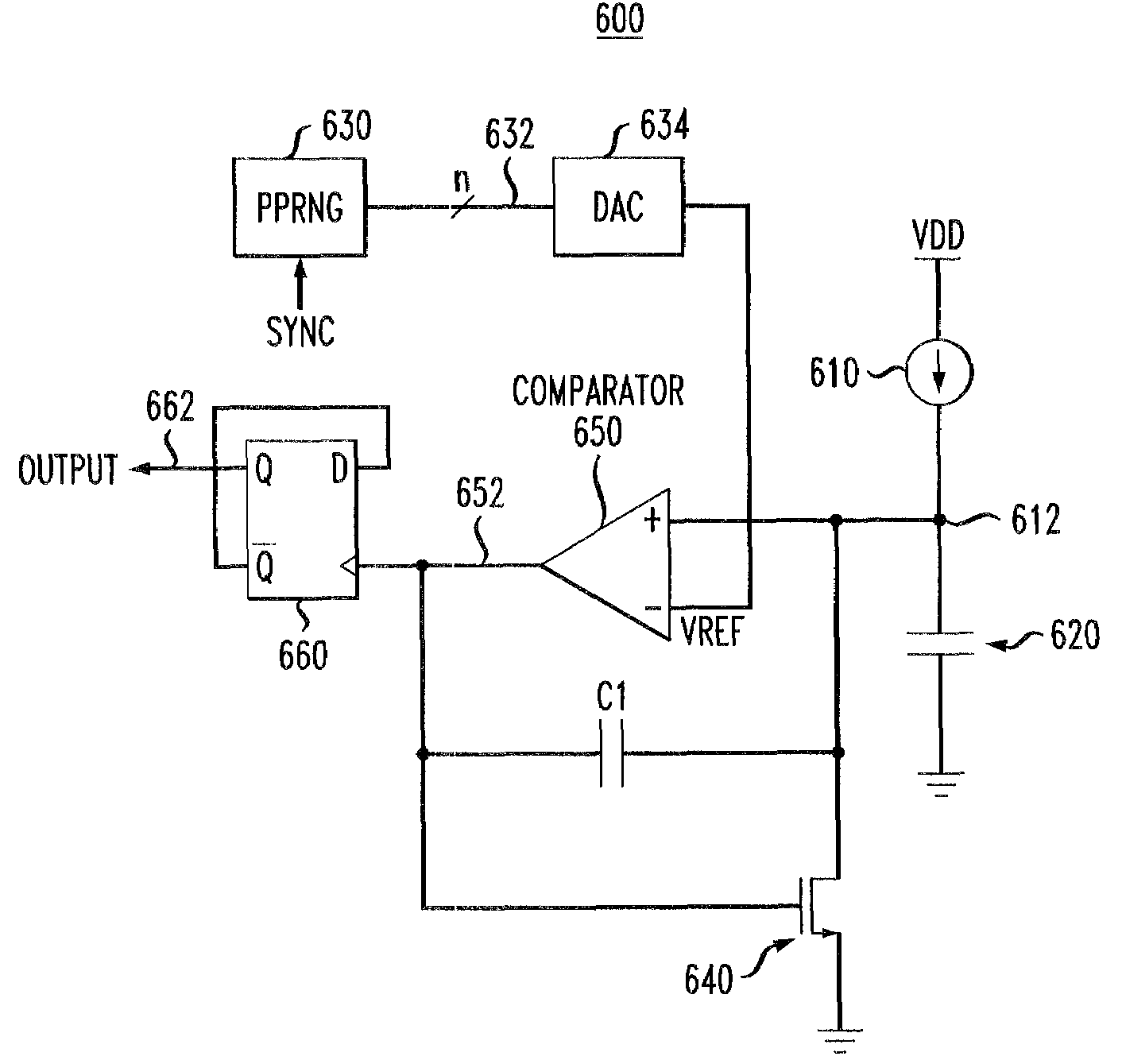
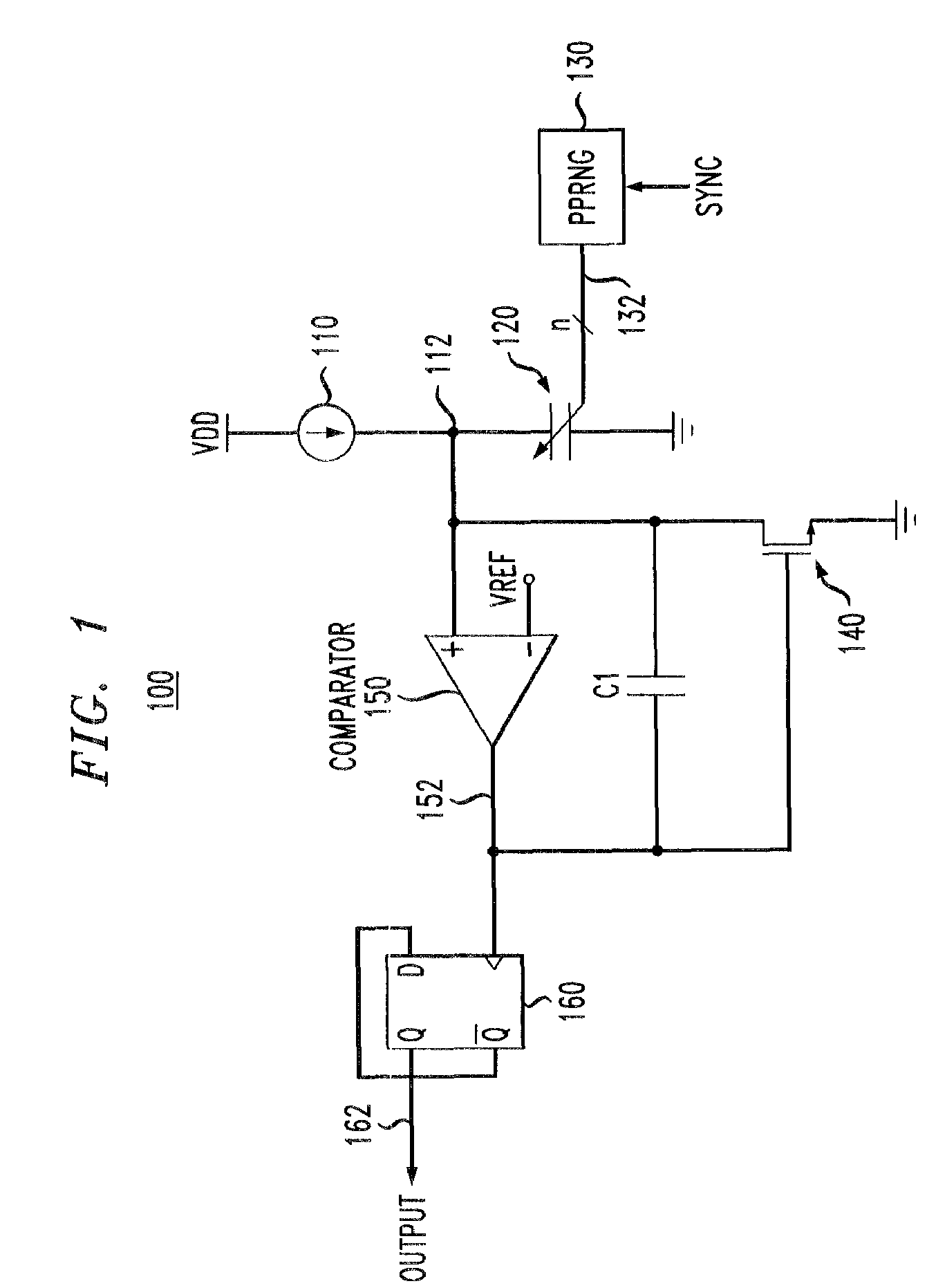
[0018]FIG. 1 shows a block diagram of a switched-current oscillator 100 according to one embodiment of the invention. As further detailed below, oscillator 100 can be used to implement spread-spectrum clock generation. Oscillator 100 has a current source 110 serially connected with a variable capacitor 120 between two power supply terminals, e.g., VDD and ground, as indicated in FIG. 1. Source 110 generates a constant current (I0) that charges capacitor 120. With a discharge device 140 (illustratively shown in FIG. 1 as a field-effect transistor) in the OFF state, the voltage across capacitor 120 (V112) increases substantially linearly as expressed by Eq. (1):

[0019]ⅆV112ⅆt=I0C120(1)

where t is time and C120 is the capacitance of capacitor 120.

[0020]Oscillator 110 has a comparator 150 that is configured to sense voltage V112 and compare it with reference voltage VREF. When voltage V112 reaches reference voltage VREF, comparator 150 generates an output signal 152 having a short pulse, ...


PUM


Abstract

A switched-current oscillator having a dc current source adapted to charge a capacitor so that the capacitor charging time is controlled based on a sequence of (pseudo)randomly selected values, each of those values defining a corresponding charging time. A discharge device is adapted to discharge the capacitor if the voltage across the capacitor reaches a threshold voltage, at which point the next value in the sequence is selected to determine the next charging time. A square-wave clock signal having spread-spectrum characteristics is generated in the oscillator by using the series of charge-discharge cycles corresponding to the sequence of randomly selected values to toggle a flip-flop operating as a delay line and zero-order hold.

Description

BACKGROUND OF THE INVENTION[0001]1. Field of the Invention[0002]The present invention relates to electronics and, more specifically, to circuits for implementing clock-frequency spreading.[0003]2. Description of the Related Art[0004]Spread-spectrum techniques in general are methods, in which energy generated in a narrow frequency band is deliberately spread over a wide frequency band. Frequency spreading can be done for a variety of reasons, e.g., to improve circuit robustness to electromagnetic interference (EMI) or jamming and to prevent hostile detection. In addition, as the speed of operation and degree of integration of electronic devices increase, the wavelengths of electromagnetic radiation generated within the electronic device decrease accordingly and become comparable with the size of wiring structures. As a result, the wiring structures can act as antennas capable of efficiently radiating and / or receiving unwanted electromagnetic radiation, which can cause high levels of ...

Claims


Application Information

Patent Timeline
Patent Type & Authority Patents(United States)
IPC IPC(8): H03B29/00
CPCH03K4/502
Inventor CHAVA, CHAITANYALOPATA, DOUGLAS D.
Owner AVAGO TECH INT SALES PTE LTD
Why Eureka
Try Eureka