
System and method for installing a wind turbine at an offshore location

a wind turbine and offshore location technology, applied in the field of wind turbines, can solve the problems of uneconomical traditional monopile foundations, limited manufacturing capability, and inability to manufacture monopiles of approximately 50 millimeters in thickness and 5.5 meters in diameter

Inactive Publication Date: 2009-03-24
GENERAL ELECTRIC CO
View PDF21 Cites 44 Cited by
  • Summary
  • Abstract
  • Description
  • Claims
  • Application Information

AI Technical Summary

Benefits of technology

Enables stable and cost-effective installation of wind turbines at deeper water depths with reduced material costs and improved scalability, as the design is less sensitive to water depth and soil conditions, and provides enhanced fatigue resistance and structural stability.

Problems solved by technology

However, for increasing water depths, a simple, traditional monopile foundation may prove uneconomical due to the correspondingly larger pile diameters and thicknesses that are required.
At present, manufacturing capability is limited to fabricating monopiles of approximately 50 millimeters in thickness and 5.5 meters in diameter.
Even if larger piles were to become available, the feasibility of such foundations is limited due to the limited availability and increasing expense of larger offshore pile driving hammers.
In the past, the fatigue design of tripod joints and other welded connections in such structures have presented difficulty in design.
In addition, the varying soil conditions and water depths in an offshore wind farm could result in varying brace diameters and joint geometries.
As a result, mass production of such tripod type structures may prove uneconomical.

Method used


Image

  • System and method for installing a wind turbine at an offshore location
  • System and method for installing a wind turbine at an offshore location
  • System and method for installing a wind turbine at an offshore location

Examples


Embodiment Construction

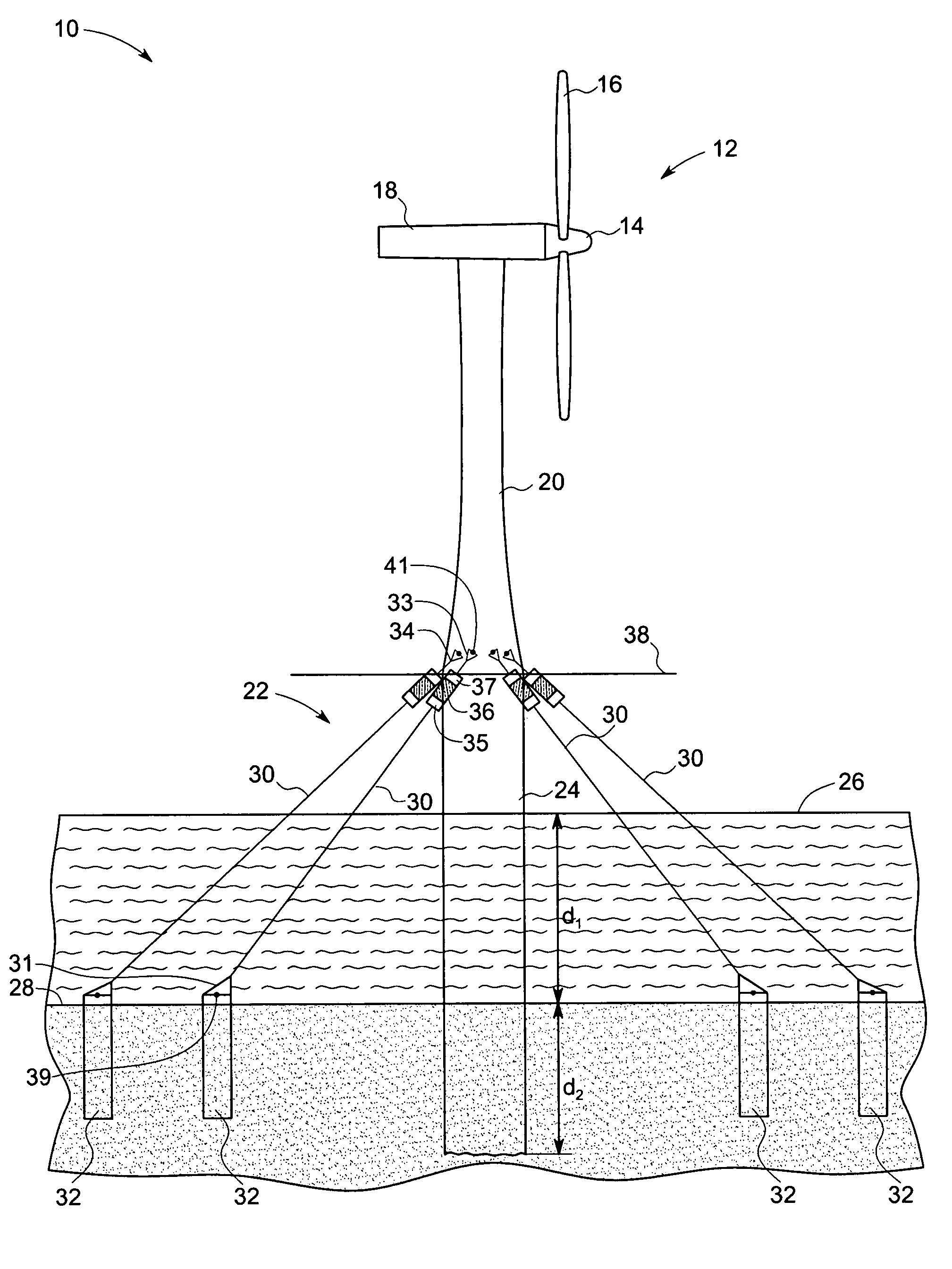
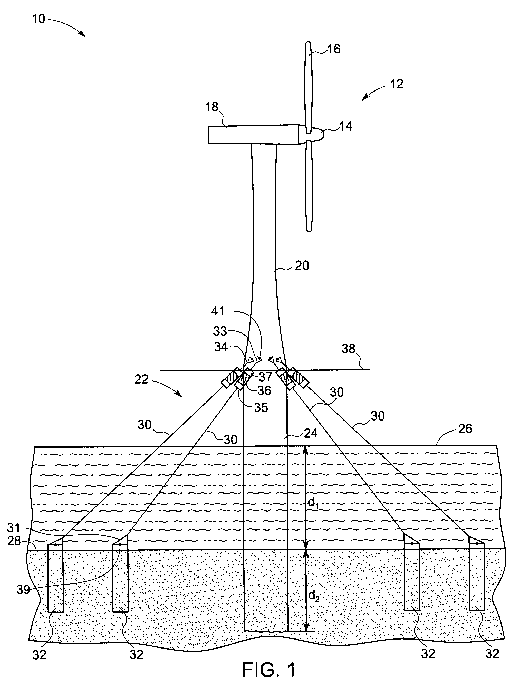
[0015]The technique described below provides a novel approach toward mounting a superstructure, such as a wind turbine tower, on a central pile or caisson at an offshore location, by incorporating taut or tensioned mooring lines. The overall lateral shear and overturning moment from the wind turbine are translated to varying tensile loads in the taut mooring lines. With varying water depths, the distance at which the mooring lines are anchored to the soil is increased in order to provide the required stiffness and the load carrying capacity. As the mooring lines are of a small diameter (approximately 3 to 5 inches), the resulting hydrodynamic loads on these lines are minimized and are essentially dominated by the wave loading on the central caisson. As will be appreciated, the present design is substantially independent of the depth of installation, and is relatively economical as in terms of material cost in comparison to using monopile / tripod foundation structures at deeper depths...


PUM


Abstract

A wind turbine system includes a wind turbine generator having a rotor and a nacelle mounted atop wind tower. The wind tower is mounted on a central caisson. The wind turbine system further includes a plurality of tensioned mooring lines flexibly secured to the central caisson. The mooring lines are further secured to a plurality of anchors fixed on to a sea bed. The anchors are adapted to support lateral loads on the wind turbine system.

Description

BACKGROUND[0001]The present invention relates generally to wind turbines, and particularly to techniques for installing and anchoring foundations for offshore wind turbine systems. Advantageously, certain embodiments of the present technique may be employed to increase the water depth at which offshore wind turbines may be located.[0002]Wind turbines are generally regarded as an environmentally safe and a desirable source of renewable energy. In summary, a wind turbine harnesses the kinetic energy of wind and transforms this kinetic energy into electrical energy. Thus, electrical power can be generated with virtually zero emissions, unlike existing natural gas-fired or coal-fired power generation technologies. To maximize the efficacy of power generation and to simplify connection to a power grid, several wind turbines are often located in proximity to one another in what are generally referred to in the pertinent art as “wind farms.” Advantageously, these wind farms are located in ...

Claims


Application Information

Patent Timeline
Patent Type & Authority Patents(United States)
IPC IPC(8): H02P9/04
CPCF03D11/045E02B2017/0091Y02E10/726Y02E10/728F03D13/22Y02E10/72
Inventor KOTHNUR, VASANTH SRINIVASAANDERSON, DAVID DELOYDZHENG, DANIANALI, MOHAMED AHMED
Owner GENERAL ELECTRIC CO
Learn More