Objective lens, optical pickup device, and optical disc apparatus
- Summary
- Abstract
- Description
- Claims
- Application Information
AI Technical Summary
Benefits of technology
Problems solved by technology
Method used
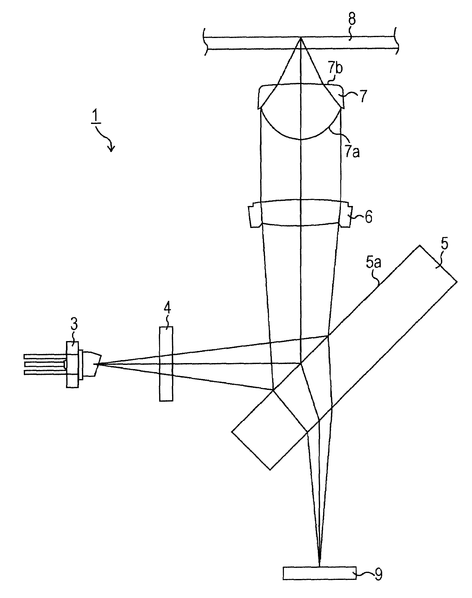
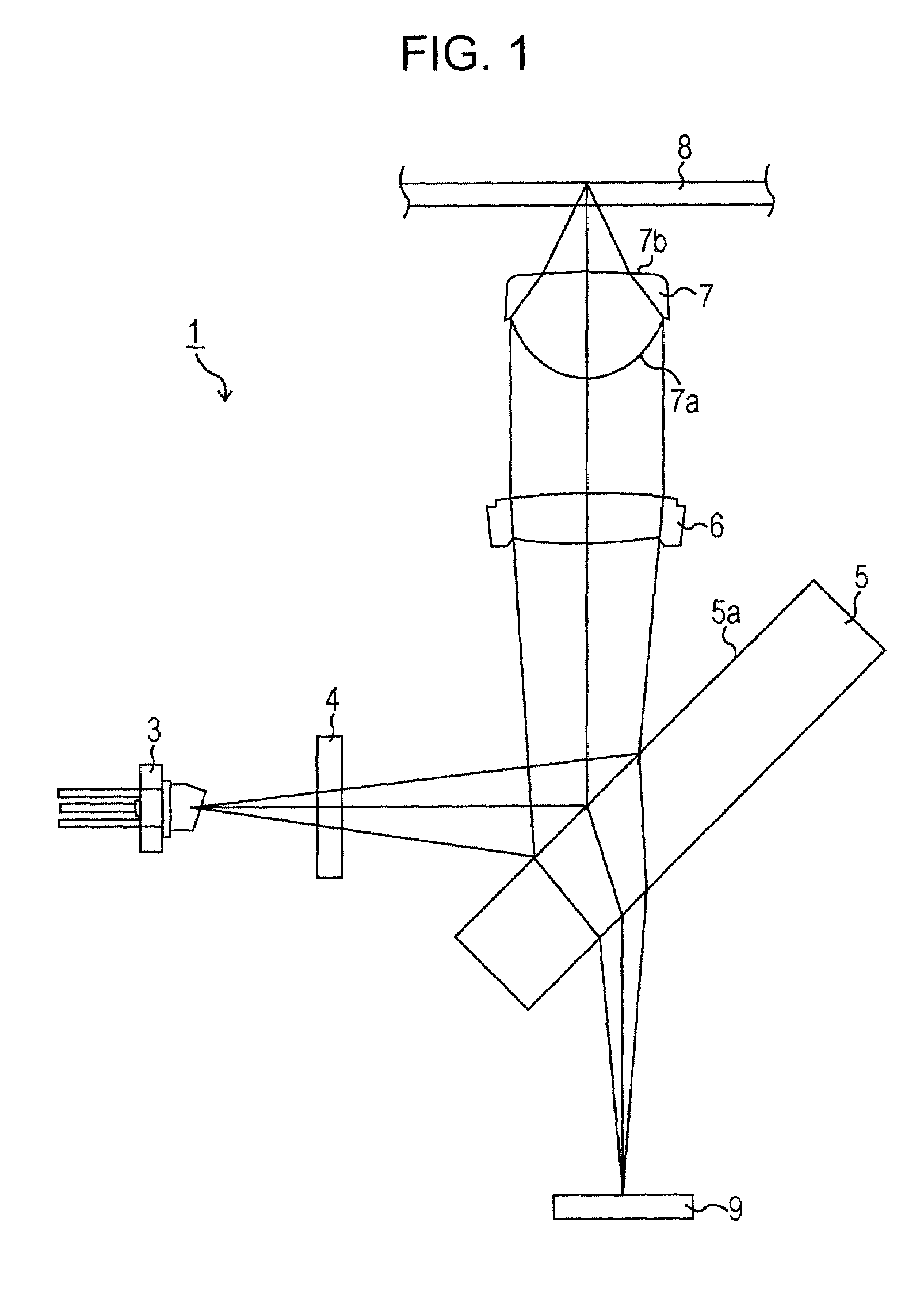
Image

Examples
first embodiment
[0088]In the objective lens according to the first embodiment, “f”, “n”, “d”, “t”, and “NA” are as follows.
[0089]f: 2.2 (mm)
[0090]n: 1.602
[0091]d: 2.59 (mm)
[0092]t: 87.5 (μm)
[0093]NA: 0.85
[0094]“R”, “K”, and “Ai” indicating the shape of the first surface at the incidence side of the objective lens of the first embodiment are as follows.
[0095]The Shape of the First Surface
[0096]R: 1.526 (mm)
[0097]K: −0.716
[0098]A4: 1.060×10⁻²
[0099]A6: −1.873×10⁻⁴
[0100]A8: 2.403×10⁻³
[0101]A10: −1.457×10⁻³
[0102]A12: 3.074×10⁻⁴
[0103]A14: 2.148×10⁻⁴
[0104]A16: −1.565×10⁻⁴
[0105]A18: 3.939×10⁻⁵
[0106]A20: −3.651×10⁻⁶
[0107]“R”, “K”, and “Ai” indicating the shape of the second surface at the emission side of the objective lens of the first embodiment are as follows.
[0108]The Shape of the Second Surface
[0109]R: −3.643 (mm)
[0110]K: −91.568
[0111]A4: 7.597×10⁻²
[0112]A6: −8.575×10⁻²
[0113]A8: 7.321×10⁻²
[0114]A10: −4.202×10⁻²
[0115]A12: 1.337×10⁻²
[0116]A14: −1.711×10⁻³
[0117]A16: −2.222×10⁻⁴
[0118]A18: 1...
second embodiment
[0133]In the objective lens according to the second embodiment, “f”, “n”, “d”, “t”, and “NA” are as follows.
[0134]f: 2.2 (mm)
[0135]n: 1.597
[0136]d: 2.59 (mm)
[0137]t: 100 (μm)
[0138]NA: 0.85
[0139]“R”, “K”, and “Ai” indicating the shape of the first surface at the incidence side of the objective lens of the second embodiment are as follows.
[0140]The Shape of the First Surface
[0141]R: 1.514
[0142]K: −0.715
[0143]A4: 1.010×10⁻²
[0144]A6: −1.120×10⁻⁴
[0145]A8: 2.437×10⁻³
[0146]A10: −1.467×10⁻³
[0147]A12: 3.033×10⁻⁴
[0148]A14: 2.156×10⁻⁴
[0149]A16: −1.559×10⁻⁴
[0150]A18: 3.951×10⁻⁵
[0151]A20: −3.732×10⁻⁶
[0152]“R”, “K”, and “Ai” indicating the shape of the second surface at the emission side of the objective lens of the second embodiment are as follows.
[0153]The Shape of the Second Surface
[0154]R: −3.550 (mm)
[0155]K: −73.364
[0156]A4: 7.877×10⁻²
[0157]A6: −8.531×10⁻²
[0158]A8: 7.121×10⁻²
[0159]A10: −4.147×10⁻²
[0160]A12: 1.341×10⁻²
[0161]A14: −1.665×10⁻³
[0162]A16: −2.436×10⁻⁴
[0163]A18: 1.33...
third embodiment
[0173]In the objective lens according to the third embodiment, “f”, “n”, “d”, “t”, and “NA” are as follows.
[0174]f: 2.2 (mm)
[0175]n: 1.638
[0176]d: 2.59 (mm)
[0177]t: 87.5 (μm)
[0178]NA: 0.85
[0179]“R”, “K”, and “Ai” indicating the shape of the first surface at the incidence side of the objective lens of the third embodiment are as follows.
[0180]The Shape of the First Surface
[0181]R: 1.554
[0182]K: −0.661
[0183]A4: 8.089×10⁻³
[0184]A6: −9.957×10⁻⁴
[0185]A8: 3.247×10⁻³
[0186]A10: −1.774×10⁻³
[0187]A12: 2.168×10⁻⁴
[0188]A14: 3.244×10⁻⁴
[0189]A16: −1.877×10⁻⁴
[0190]A18: 4.157×10⁻⁵
[0191]A20: −3.474×10⁻⁶
[0192]“R”, “K”, and “Ai” indicating the shape of the second surface at the emission side of the objective lens of the third embodiment are as follows.
[0193]The Shape of the Second Surface
[0194]R: −5.055
[0195]K: −84.685
[0196]A4: 1.217×10⁻¹
[0197]A6: −1.372×10⁻¹
[0198]A8: 9.295×10⁻²
[0199]A10: −3.779×10⁻²
[0200]A12: 7.084×10⁻³
[0201]A14: 1.931×10⁻⁴
[0202]A16: −2.087×10⁻⁴
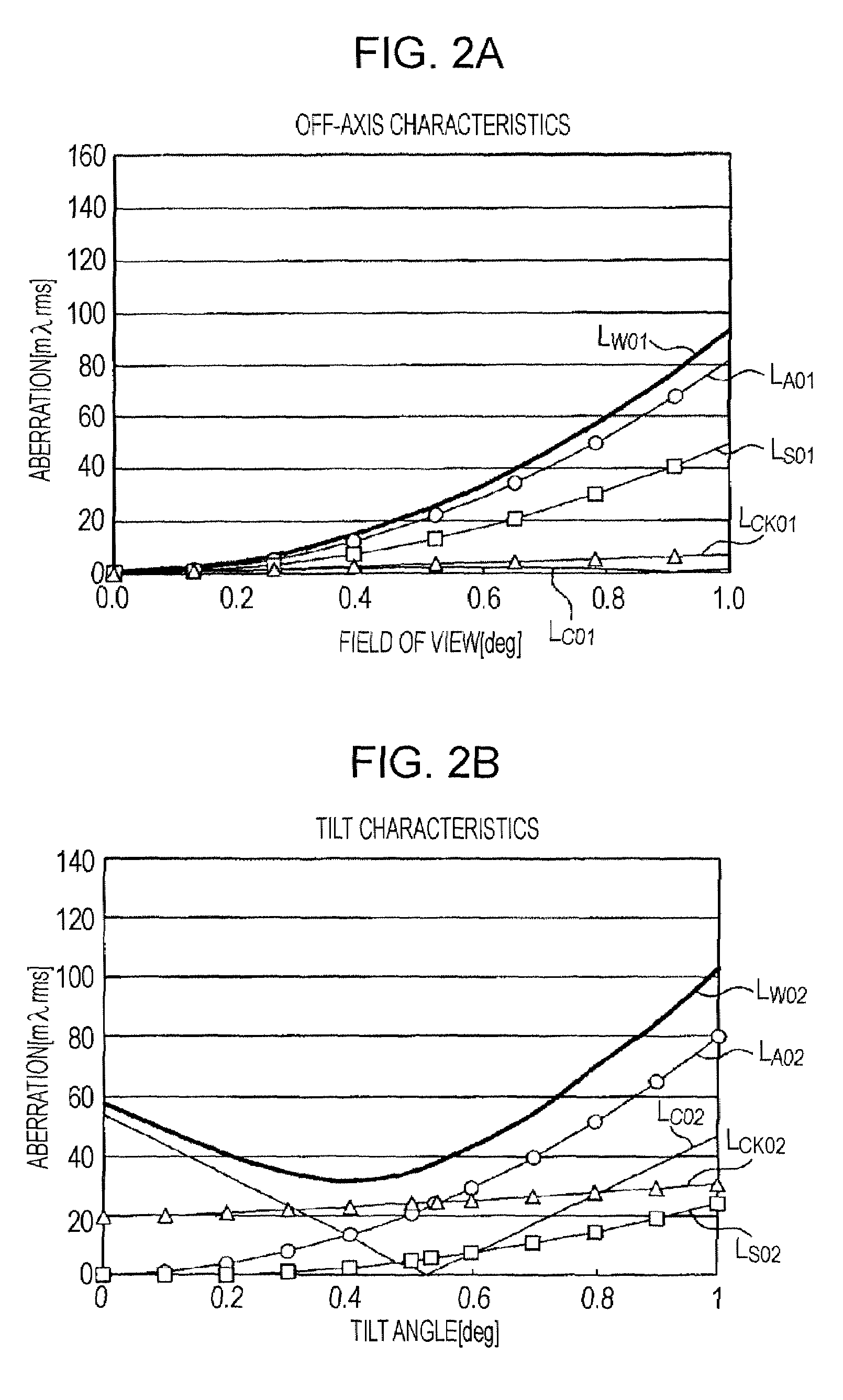
[0203]FIG. 5A shows off...
PUM
 Abstract
Description
Claims
Application Information
 - R&D Engineer
- R&D Manager
- IP Professional
- Industry Leading Data Capabilities
- Powerful AI technology
- Patent DNA Extraction
Browse by: Latest US Patents, China's latest patents, Technical Efficacy Thesaurus, Application Domain, Technology Topic.
© 2024 PatSnap. All rights reserved.Legal|Privacy policy|Modern Slavery Act Transparency Statement|Sitemap