Motor control device

a technology of motor control and control device, which is applied in the direction of motor/generator/converter stopper, dynamo-electric gear control, and dynamo-electric converter control. it can solve the problems of low accuracy, low workability, and degradation of torque control accuracy or a reduction in the maximum torque. achieve the effect of improving workability and improving accuracy

Inactive Publication Date: 2009-03-31
MITSUBISHI ELECTRIC CORP
View PDF17 Cites 19 Cited by
  • Summary
  • Abstract
  • Description
  • Claims
  • Application Information

AI Technical Summary

Benefits of technology

[0023]A motor control device according to the invention includes a velocity calculation unit that calculates an actual velocity from a detected position, that is, a position of a motor or of a load connected to the motor detected at a detector, a uvw / dq coordinate converting unit that receives a three-phase current detected in an inverter, performs coordinate conversion from a uvw three-phase coordinate system at rest into a dq synchronous rotation coordinate system, and outputs a d-axis current and a q-axis current, a current control unit that receives a d-axis current command, a q-axis current command, the d-axis current feedback, and the q-axis current feedback, performs current control such that a dq-axis current detection value coincides with a dq-axis current command, and outputs a d-axis voltage command and a q-axis voltage command, a dq / uvw coordinate converting unit that receives the d-axis voltage command, the q-axis voltage command, and the detected position, performs coordinate conversion from the dq synchronous rotation coordinate system into the uvw three-phase coordinate system at rest, and outputs a three-phase voltage command, an inverter that receives the three-phase voltage command, applies an actual three-phase voltage to the motor, and drives the motor at a variable velocity, a superimposed signal generating unit that outputs a superimposed signal of a repetitive waveform, such as a triangular wave or a sine wave, a d-axis current command generating unit that adds the superimposed signal idh generated by the superimposed signal generating unit to the d-axis current command and outputs the d-axis current command, a torque current error calculation unit that receives the actual velocity output from the velocity calculation unit and the q-axis current command and estimates a torque current error actually occurring in the motor, and an axial misalignment detecting unit that receives the d-axis current command and the torque current error and outputs an axial misalignment angle estimation value. Therefore, the motor control device having this configuration can be used in a normal operation state including a torque command. Further, accurate axial misalignment detection can be performed even when an absolute value of an axial misalignment angle is 90 degrees or more because a calculation value of the torque current error, not a q-axis current command, is employed.
[0025]The motor control device includes an axial misalignment correction unit that receives the axial misalignment angle estimation value output from the axial misalignment detecting unit and the detected position detected by the detector, calculates a position after correction, and outputs the calculated position to the dq / uvw coordinate converting unit and the uvw / dq coordinate converting unit. In this case, the dq / uvw coordinate converting unit and the uvw / dq coordinate converting unit may perform coordinate conversion based on the position after correction. Therefore, workability can be improved since it is not necessary to mount the encoder again that has been already mounted. Further, in the axial misalignment detection, the d-axis current command and the q-axis current command or data having substantially aligned phases (the same phase or opposing phases), such as the torque current error, are used. Accordingly, correction can be carried out in real time through calculation at a given timing during a normal operation.
[0027]The axial misalignment detecting unit has a first input filter that filters the d-axis current command and outputs a d-axis signal for axial misalignment detection, a variable gain calculation unit that calculates a function of the d-axis signal for axial misalignment detection, a second input filter that filters the q-axis current command or torque current error and outputs a q-axis signal for axial misalignment detection, an adaptive input calculation unit that calculates an adaptive input by multiplying the function of the d-axis signal for axial misalignment detection and the q-axis signal for axial misalignment detection, and an integrator that integrates the integral input and outputs the axial misalignment angle estimation value. Accordingly, the motor control device having this configuration can easily improve accuracy and a convergence velocity according to a writing method of the function calculated in the variable gain calculation unit.
[0029]The axial misalignment detecting unit has a first input filter that filters the d-axis current command and outputs a d-axis signal for axial misalignment detection, a second input filter that filters the q-axis current command or torque current error and outputs a q-axis signal for axial misalignment detection, an estimation output calculation unit that multiplies the d-axis signal for axial misalignment detection extracted by the input filter and the axial misalignment angle estimation value to be described below, and outputs an estimation output, an axial misalignment error calculation unit that finds a difference between the q-axis signal for axial misalignment detection extracted by the second input filter and the estimation output from the estimation output calculation unit, and outputs an axial misalignment error, a variable gain unit that multiplies the axial misalignment error output from the axial misalignment error calculation unit by a gain and outputs an integral input, and an integrator that integrates the integral input output from the variable gain unit to obtain the axial misalignment angle estimation value. Therefore, the motor control device having this configuration can prohibit an influence of noise and can perform the axial misalignment detection with high accuracy. Further, the motor control device having this configuration can perform the detection while performing correction in real time, can perform only the detection of the axial misalignment angle without correction, and find wide applications.

Problems solved by technology

If accuracy of the initial magnetic pole position detection is poor, an axial misalignment phenomenon that a dq-axis (a dm-pm axis) of an actual motor and a dq-axis (a dc-qc axis) for control are misaligned occurs.
Accordingly, an adverse effect, such as degradation of torque control accuracy or a reduction in a maximum torque, occurs.
If mounting accuracy is low, axial misalignment also occurs.
However, since estimation can be carried out only when a command torque current (q-axis current command iqc*) is zero, the initial magnetic pole position estimation device cannot perform estimation during a normal operation, such as velocity control.
Accordingly, there is a problem in that an inefficient work occurs.
Therefore, there is a problem in that robustness against noise, friction variation, disturbance load, and / or the like is low.
Accordingly, there is a problem in that estimation accuracy is significantly low when accurate parameters are not found.
However, the motor control device cannot detect an actual velocity shift or position movement since it does not include a velocity detecting unit or a position detecting unit and cannot employ velocity feedback information.
Accordingly, the disclosed motor control device has a problem in that accuracy of magnetic pole position estimation is rarely improved.
The motor control device disclosed in Patent Document 2 has a problem in that it is rarely applied to a motor not having an electrical saliency or having a small electrical saliency, since it uses the electrical saliency.
Accordingly, the disclosed motor control device has a problem in that it is affected by current detection noise.
Accordingly, there is a problem in that a sequence is complicated since a solution for detecting the superimposed signal and the detection signal at specific phase timings, a solution for calculating a peak value or a shift rate, and so on are required.

Method used


Image

  • Motor control device
  • Motor control device
  • Motor control device

Examples


first embodiment

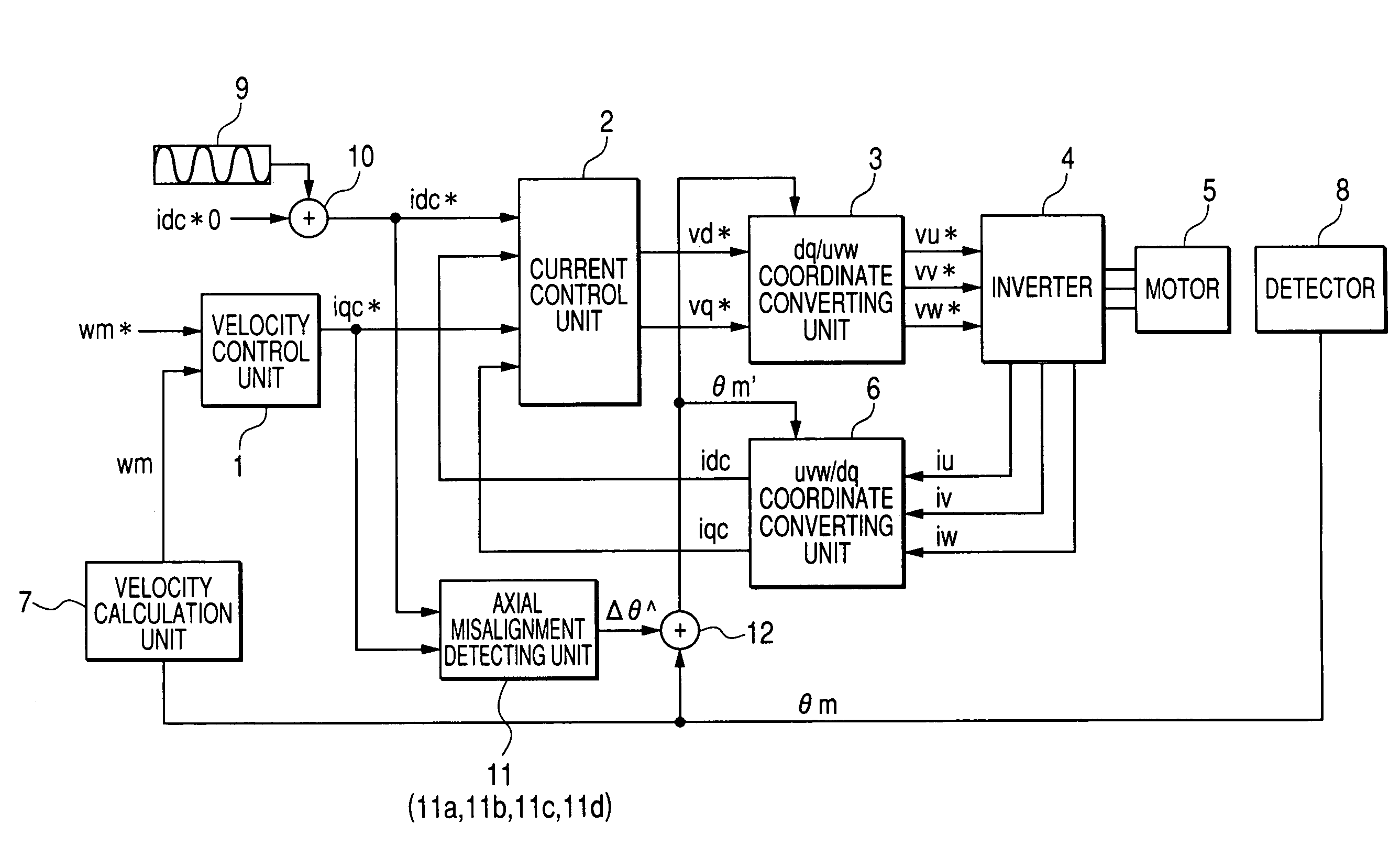
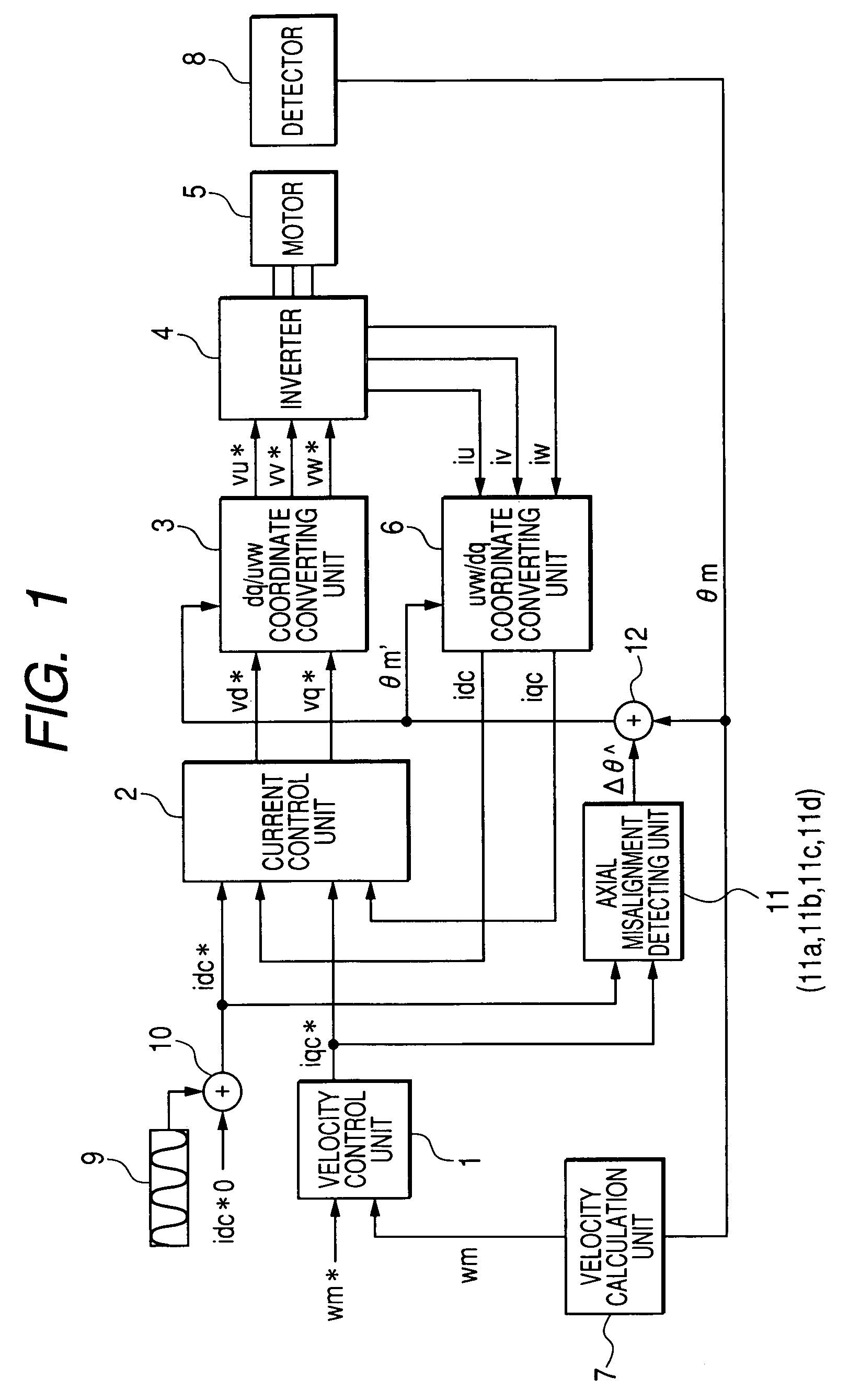
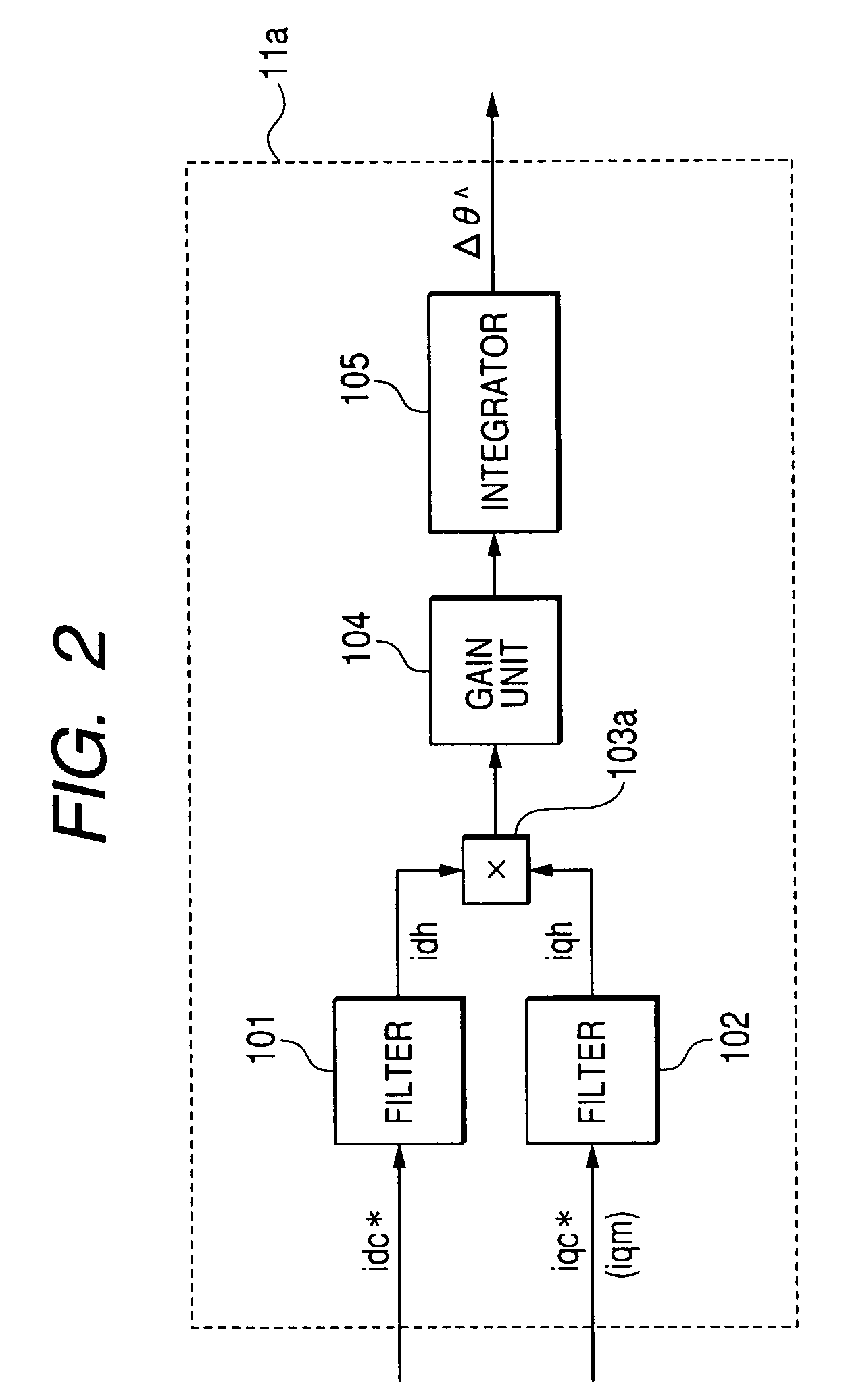
[0041]FIG. 1 is a block diagram showing the configuration of a motor control device according to a first embodiment of the invention. FIG. 2 is a block diagram showing an example of the configuration of an axial misalignment detecting unit 11a in the motor control device according to the first embodiment of the invention. FIG. 3 is a diagram illustrating the relationship between a dq-axis (dm-qm axis) of an actual motor and a dq-axis (dc-qc axis) for control.

[0042]The processing operation of the motor control device according to the first embodiment will be described below with reference to FIGS. 1 to 3.

[0043]In FIG. 1, a velocity control unit 1 receives a velocity command wm* and an actual velocity wm, performs current control to cause the actual velocity wm to follow the velocity command wm* using PI control or the like, and outputs a q-axis current command iqc*. Further, a current control unit 2 receives a d-axis current command idc*, the q-axis current command iqc*, a d-axis cur...

second embodiment

[0072]The processing operation of the axial misalignment detecting unit 11b in the motor control device according to the second embodiment will be described with reference to FIG. 4. In FIG. 4, reference numerals 101, 102, 104, and 105 are the same as those of FIG. 2 and the descriptions thereof will be omitted for simplicity. The axial misalignment detecting unit 11b shown in FIG. 4 further includes a sign detector 106 serving as a first sign detector and a sign detector 107 serving as a second sign detector. The sign detector 106 and the sign detector 107 are interposed between the input filters 101, 102 and the adaptive input calculation unit 103a in the axial misalignment detecting unit 11a shown in FIG. 2.

[0073]The sign detectors 106, 107 receive a d-axis signal for axial misalignment detection idh and a q-axis signal for axial misalignment detection iqh, respectively, which are extracted through the input filters 101, 102, respectively, detect signs of the d-axis signal for ax...

third embodiment

[0078]The processing operation of the axial misalignment detecting unit 11c in the motor control device according to the third embodiment will be described with reference to FIG. 5.

[0079]The input filters 101, 102 perform extracting processes on the d-axis current command idc* and the q-axis current command iqc* (or torque current error iqm), respectively, which are input to the axial misalignment detecting unit 11c, and output the d-axis signal for axial misalignment detection idh and the q-axis signal for axial misalignment detection iqh.

[0080]An estimation output calculation unit 108 multiplies the d-axis signal for axial misalignment detection idh that is extracted by the input filter 101 and an axial misalignment angle measurement value Δθ^ to be described later, and outputs an estimation output (idh×Δθ^). Further, an axial misalignment error calculation unit 109 outputs axial misalignment error based on a difference between the q-axis signal for axial misalignment detection iq...


PUM


Abstract

In a motor control device according to the invention, upon velocity control of a motor, a superimposed signal generating unit 9 outputs a superimposed signal idh of a repetitive waveform, such as a triangular wave or a sine wave. A d-axis current command generating unit 10 adds the superimposed signal idh generated by the superimposed signal generating unit 9d to a d-axis current command idc*0 and outputs a d-axis current command idc*. An axial misalignment detecting unit 11 (11a, 11b, 11c, and 11d) receives the d-axis current command idc* and a q-axis current command iqc* and outputs an axial misalignment angle estimation value Δθ^. An axial misalignment correction unit 12 receives the axial misalignment angle estimation value Δθ^ and an actual detected position θm and outputs a position after correction θm′. Therefore, detection and correction can be performed in real time through calculation at a given timing during a normal operation.

Description

TECHNICAL FIELD[0001]The present invention generally relates to a motor control device that controls a synchronous motor, and more particularly, to a motor control device having an axial misalignment detecting unit for detecting an axial misalignment angle between a dq-axis of a synchronous motor, which is to be a control object, and a dq-axis for control.BACKGROUND ART[0002]As a servo control of a synchronous motor, a vector control that separates a current in a field magnetic flux direction (d-axis) of the motor and a direction perpendicular to the field magnetic flux direction (q-axis) and performs current control for the d axis and the q-axis is generally performed. In the vector control, it is necessary to detect magnetic pole positions in order to generate a torque effectively.[0003]A linear motor is often used in combination with an incremental encoder that cannot detect an absolute position of the motor at the time of power activation. Since the incremental encoder can detec...

Claims


Application Information

Patent Timeline
Patent Type & Authority Patents(United States)
IPC IPC(8): H02P27/04H02P6/18H02P6/06H02P6/08H02P6/17H02P6/182H02P6/28H02P21/00H02P21/06H02P21/18H02P21/22H02P21/24H02P21/34H02P23/14H02P23/16H02P25/026
CPCH02P21/06H02P21/0003
Inventor TERADA, KEINAGANO, TETSUAKIHARADA, YASUNOBUTAKAHASHI, KAZUTAKA
Owner MITSUBISHI ELECTRIC CORP
Why Eureka
Try Eureka