
Differential crystal oscillator

a crystal oscillator and different technology, applied in the direction of logic circuit pulse generation, oscillator generator, etc., can solve the problems of large amount of digital noise in the output of such “digital” oscillators, high square output of oscillators, and general undesirable harmonic components, and achieve the effect of superior common mode rejection

Active Publication Date: 2009-03-31
CYPRESS SEMICON CORP
View PDF18 Cites 5 Cited by
  • Summary
  • Abstract
  • Description
  • Claims
  • Application Information

AI Technical Summary

Benefits of technology

[0008]Thus a need exists for a differential crystal oscillator with high noise rejection characteristics that produces little undesirable noise. In conjunction with the aforementioned need, a further need exists for a differential crystal oscillator that may be implemented in an integrated circuit in a straight-forward manner. A still further need exists for meeting the previously identified needs with an oscillator design that provides differential signals for use by other differential circuits on an integrated circuit, without requiring additional circuitry to convert signals from single ended to differential.
[0009]Accordingly, embodiments of the present invention provide for a differential crystal oscillator with high noise rejection characteristics that produces reduced undesirable noise. In conjunction with the aforementioned characteristics, further embodiments of the present invention provide for a differential crystal oscillator that can be implemented in an integrated circuit in a straight-forward manner, deriving additional benefits from the characteristics of integrated circuits. Still further embodiments of the present invention provide for meeting the previously identified benefits with an oscillator design that provides differential signals for use by other differential circuits on an integrated circuit, without requiring additional circuitry to convert signals from single ended to differential.
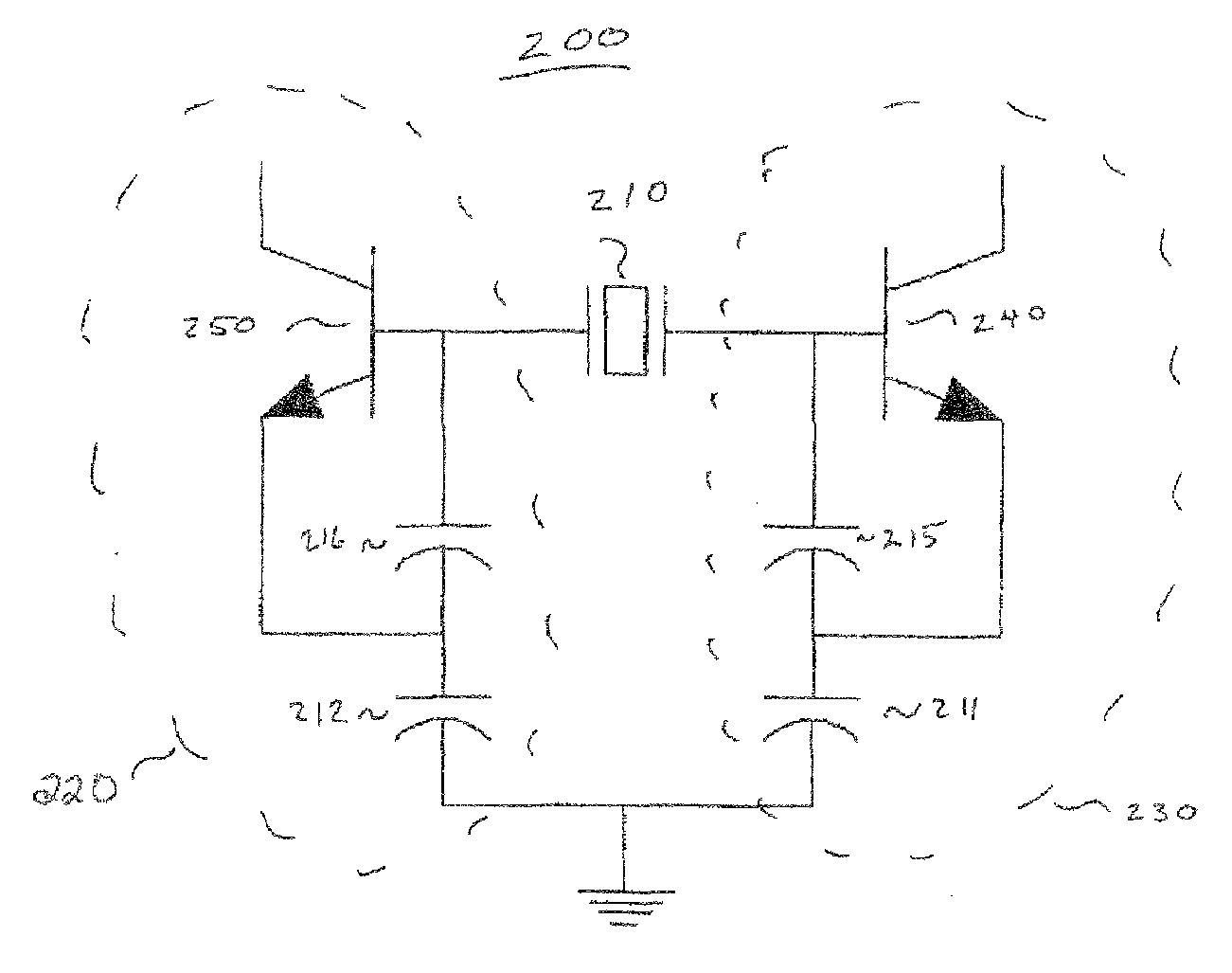
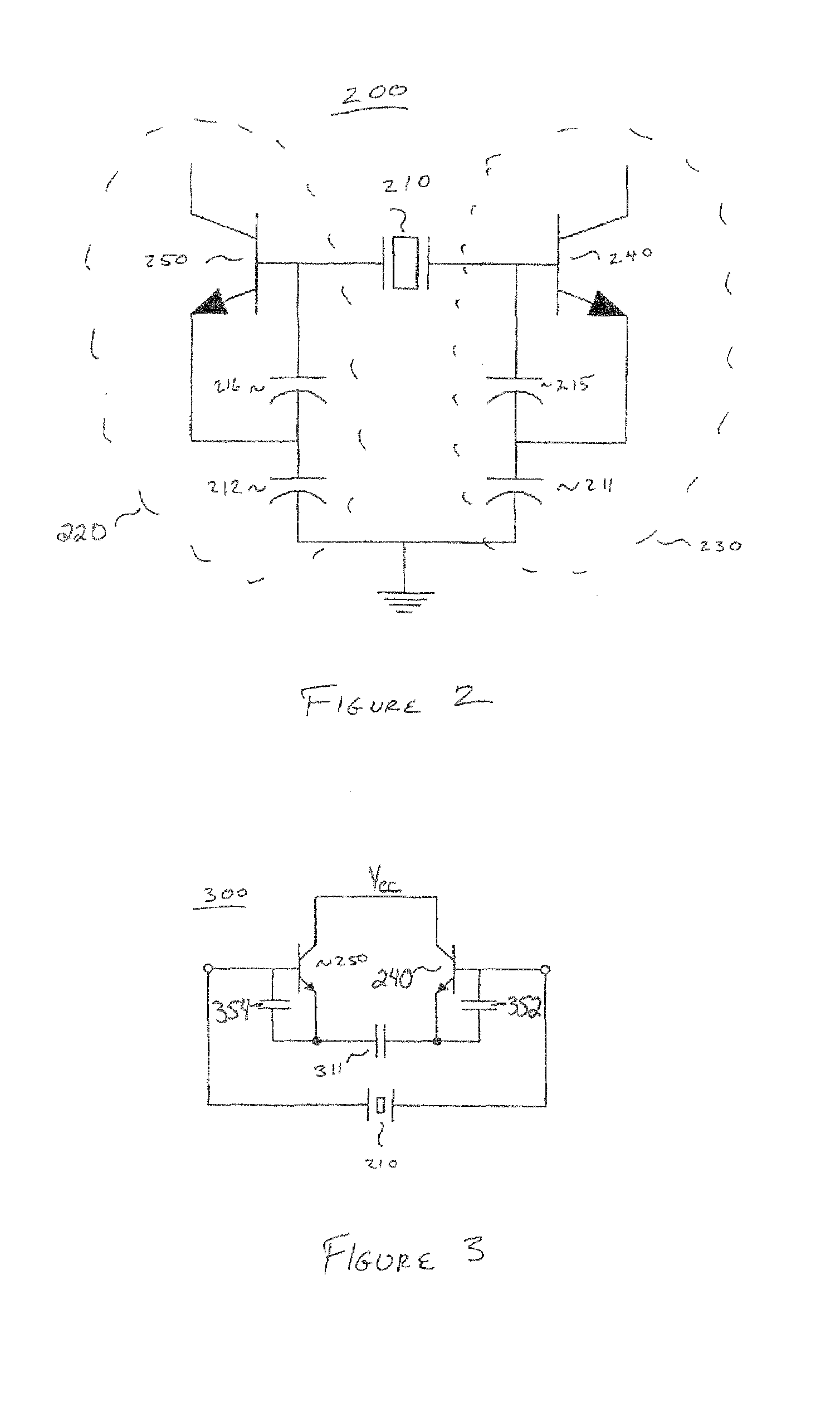
[0011]Advantageously, the novel circuit is fully balanced. The circuit further takes advantage of the circuit symmetry available in integrated circuits. It also has superior common mode rejection and supply rejection. The oscillator naturally furnishes differential signals for use by other differential circuits on an integrated circuit, obviating a circuit to create differential signals from single ended signals.

Problems solved by technology

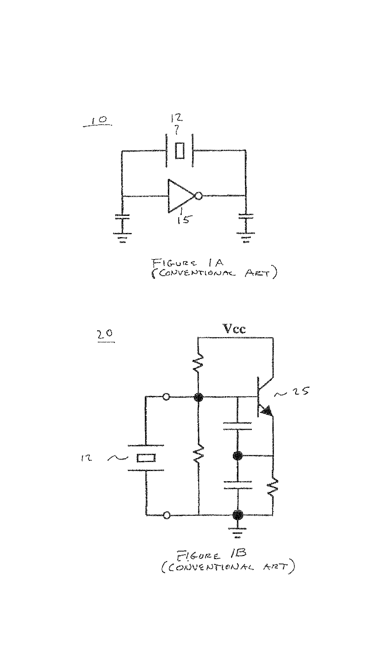
Unfortunately, this class of “digital” oscillator produces a very square output with high harmonic content, often swinging from voltage rail to ground rail.
Although generally acceptable for digital electronics, such harmonic components are generally undesirable for “analog” applications, e.g., phase locked loops and radio circuitry.
In addition, the output of such “digital” oscillators contains large amounts of digital noise.
Further, when implemented as part of an integrated circuit, due to its single ended or unbalanced nature, it produces deleterious electrical noise, which can be coupled via the IC substrate to other circuits on the integrated circuit, degrading their function.
However, when implemented as part of an integrated circuit, due to its single ended or unbalanced nature, it produces deleterious electrical noise which can be coupled via the IC substrate to other circuits on the integrated circuit, degrading their function.
Unfortunately, for a substantial class of applications, for example, phase locked loops and radio circuitry, existing crystal oscillator designs are not well suited for implementation in an integrated circuit.
Such known crystal oscillator designs typically suffer deleterious noise susceptibility.
Input noise may be amplified and / or cause an oscillator to lock on to an undesired frequency.
Further, they often generate unacceptable noise components on their output signals and frequently couple additional noise via the integrated circuit substrate.

Method used


Image

  • Differential crystal oscillator
  • Differential crystal oscillator
  • Differential crystal oscillator

Examples


Embodiment Construction

[0018]In the following detailed description of the present invention, method and apparatus of differential crystal oscillator, numerous specific details are set forth in order to provide a thorough understanding of the present invention. However, it will be recognized by one skilled in the art that the present invention may be practiced without these specific details or with equivalents thereof. In other instances, well-known methods, procedures, components, and circuits have not been described in detail as not to unnecessarily obscure aspects of the present invention.

Differential Crystal Oscillator

[0019]The present invention is described in the context of frequency generation on integrated circuits. However, it is appreciated that the present invention may be utilized in other types of electronics, including discrete components, where it may be necessary or desirable to produce low noise periodic signals.

[0020]FIG. 2 illustrates an exemplary differential crystal oscillator circuit ...


PUM


Abstract

A differential crystal oscillator electronic circuit. Embodiments of the present invention include circuits comprising two substantially similar oscillator circuits. The oscillator circuits may be coupled to a common crystal or ceramic resonator. Embodiments of the present invention are especially well suited to implementation within integrated circuits where their superior common mode and supply rejection function beneficially in opposition to the naturally high coupling characteristics of integrated circuits. Further, by naturally furnishing differential signals, these low noise signals may be used directly by other differential circuits on an integrated circuit, without requiring additional single ended to differential conversion circuitry.

Description

FIELD OF THE INVENTION[0001]Embodiments of the present invention generally relate to the field of integrated circuit design. More specifically, embodiments of the present invention pertain to crystal oscillator designs.BACKGROUND ART[0002]A quality frequency source is often required for applications such as the local oscillator in a radio frequency transceiver, the frequency reference in a phase-locked loop, or the master clock source in a microprocessor or data-acquisition system. A crystal oscillator is an electronic circuit designed to produce such a stable, accurate frequency signal. In a crystal oscillator, the piezo-electric properties of a quartz crystal or a ceramic resonator used as a circuit element primarily determine the operating frequency. Because of their superior accuracy and stability characteristics, crystal oscillators are standard in a wide variety of electronic devices, from digital watches to “super” computers and almost all radio frequency devices.[0003]Conven...

Claims


Application Information

Patent Timeline
Patent Type & Authority Patents(United States)
IPC IPC(8): H03B5/32
CPCH03B5/36H03B2200/0008H03B2200/0098
Inventor GEHRING, MARK RICHARD
Owner CYPRESS SEMICON CORP
Learn More