On-die termination snooping for 2T applications in a memory system implementing non-self-terminating ODT schemes

a memory system and odt scheme technology, applied in the field of memory systems, can solve the problems of high capacitance loading of the command/adress bus, increasing the complexity of the memory controller and the hardware required to operate the memory controller, and affecting the operation of 2t operations

Active Publication Date: 2009-04-07
MICRON TECH INC
View PDF5 Cites 65 Cited by
  • Summary
  • Abstract
  • Description
  • Claims
  • Application Information

AI Technical Summary

Problems solved by technology

Thus, the command / address bus tends to encounter high capacitive loading.
Thus, the complexity of the memory controller and the hardware required to operate the memory controller increases, especially as the number of memory modules increases.
However, 2T operation is problematic with the non-self terminating and the combined self / non-self terminating ODT schemes because the first clock pulse in the 2T cycle may be invalid.

Method used


Image

  • On-die termination snooping for 2T applications in a memory system implementing non-self-terminating ODT schemes
  • On-die termination snooping for 2T applications in a memory system implementing non-self-terminating ODT schemes
  • On-die termination snooping for 2T applications in a memory system implementing non-self-terminating ODT schemes

Examples


Embodiment Construction

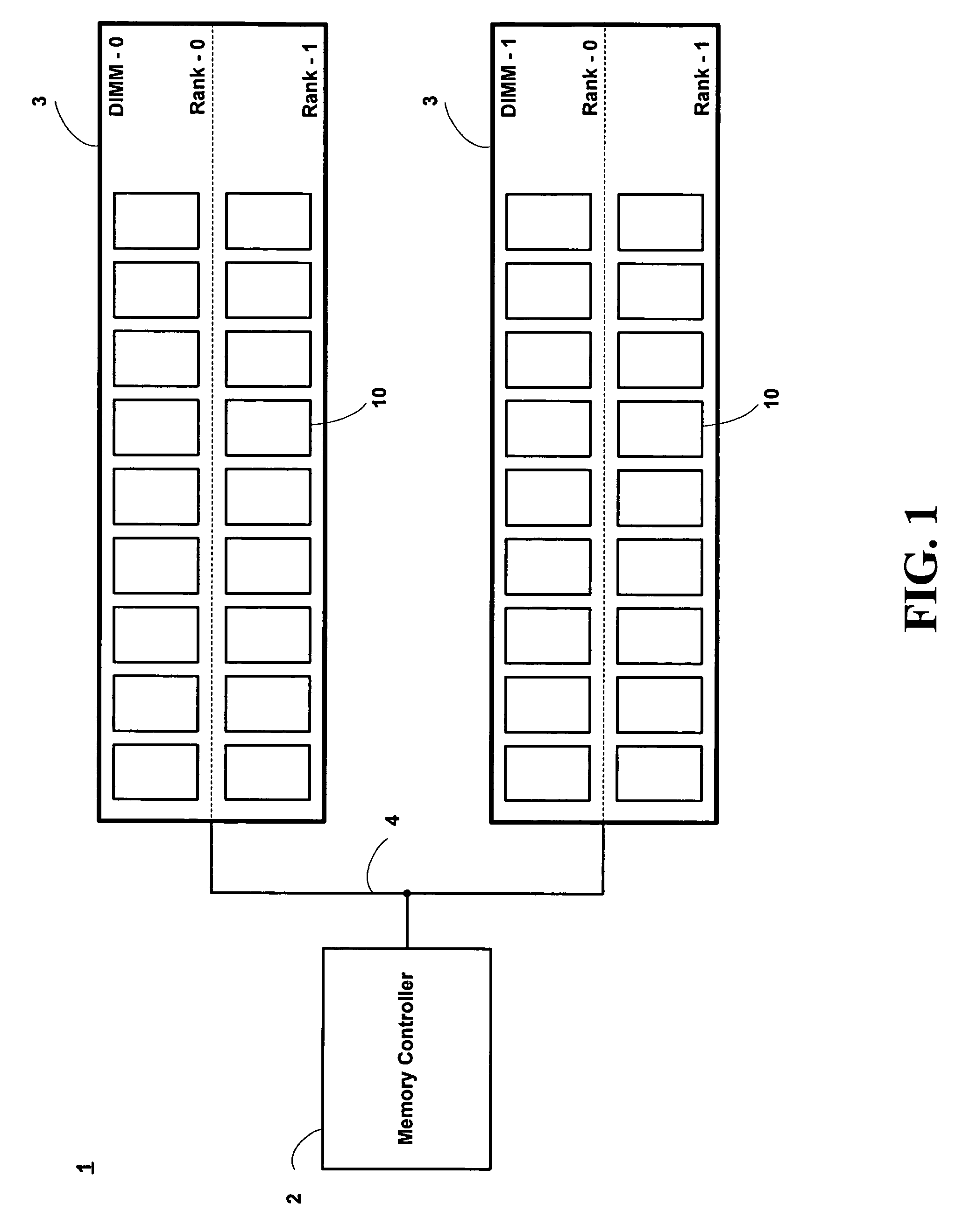
[0030]FIG. 1 is a simplified block diagram of a memory system 1 according to one embodiment. The memory system 1 includes a memory controller 2 and two (2) dual-inline-memory-modules 3 (i.e., DIMM-0, DIMM-1). Each memory module 3 is divided into two (2) ranks (Rank-0, Rank-1), each rank being comprised of nine (9) synchronous dynamic random access memory devices (SDRAM) 10. The use of an SDRAM is for exemplary purposes only and is not intended, in any manner, to limit the scope of the present invention. It should be apparent to those skilled in the art that other types of memory devices may be used, and the number of memory modules and ranks varied, while remaining within the scope of the present invention.

[0031]The memory controller 2 and memory modules 3 communicate via a system bus 4. In the current embodiment, the system bus 4 carries command signals, address signals, and data signals, among others. The system bus 4 may be sub-divided into two or more buses, for example a comman...


PUM


Abstract

A method and apparatus for controlling the on-die termination of a memory system. The method comprises snooping a command bus in response to a first plurality of command signals clocked at 1T and enabling the on-die termination in response to a second plurality of command signals clocked at 2T and the first plurality of command signals. The apparatus may be a memory device comprising a memory array responsive to a plurality of command signals, a data bus having at least one of a data pad, a data strobe output pad, and an input data mask pad, an activation circuit responsive to certain of the plurality of command signals and operable to produce a control signal, and a termination circuit responsive to the control signal and operable to apply an effective resistance to at least one of the data pad, the data strobe output pad, and the input data mask pad.

Description

BACKGROUND OF THE INVENTION[0001]The present invention relates generally to memory systems and more particularly to memory systems which incorporate on-die termination.[0002]A typical memory system includes a memory controller and one or more memory modules (for example, dual in-line memory modules or DIMMs). Each memory module may include a plurality of memory devices (such as a dynamic random access memory (DRAM), synchronous dynamic random access memory (SDRAM), double data rate synchronous dynamic random access memory (DDR SDRAM), etc.). For example, a DIMM typically has eighteen (18) memory devices divided into two ranks. The first rank, comprised of nine (9) memory devices, is located on the front side of the DIMM and the second rank, also comprised of nine (9) memory devices, is located on the back side of the DIMM.[0003]Data is written to and read from the memory devices under the direction of the memory controller. Commands and addresses are transmitted unidirectionally (i....

Claims


Application Information

Patent Timeline
Patent Type & Authority Patents(United States)
IPC IPC(8): G06F13/00G06F12/00G06F13/40
CPCG06F13/4086
Inventor LABERGE, PAUL A.
Owner MICRON TECH INC
Why Eureka
Try Eureka