High-strength concrete wall formwork

a formwork and high-strength technology, applied in the direction of walls, parkings, ceilings, etc., can solve the problems of difficulty for civil engineers to quantify with precision how much they contribute to wall resistance, and achieve the effects of improving the rigidity of the integrated formwork, facilitating the work of civil engineers, and excellent resistance to high stresses

Inactive Publication Date: 2009-04-14
POLYFINANCE COFFOR HLDG SA
View PDF51 Cites 15 Cited by
  • Summary
  • Abstract
  • Description
  • Claims
  • Application Information

AI Technical Summary

Benefits of technology

[0006]The formworks of the above-mentioned prior art present an excellent resistance to high stresses in particular due to high intensity earthquake shocks. However, contrary to the rectilinear frameworks usually used, the zigzag form of the connection elements between the walls makes it difficult for the civil engineers to quantify with precision how much they contribute to wall resistance. The aim of this invention is to increase the rigidity of the integrated formworks at the time of their installation, to facilitate the work of the civil engineers in order to determine easily the contribution of the horizontal frameworks and to reduce manufacturing costs.

Problems solved by technology

However, contrary to the rectilinear frameworks usually used, the zigzag form of the connection elements between the walls makes it difficult for the civil engineers to quantify with precision how much they contribute to wall resistance.

Method used


Image

  • High-strength concrete wall formwork
  • High-strength concrete wall formwork
  • High-strength concrete wall formwork

Examples


Embodiment Construction

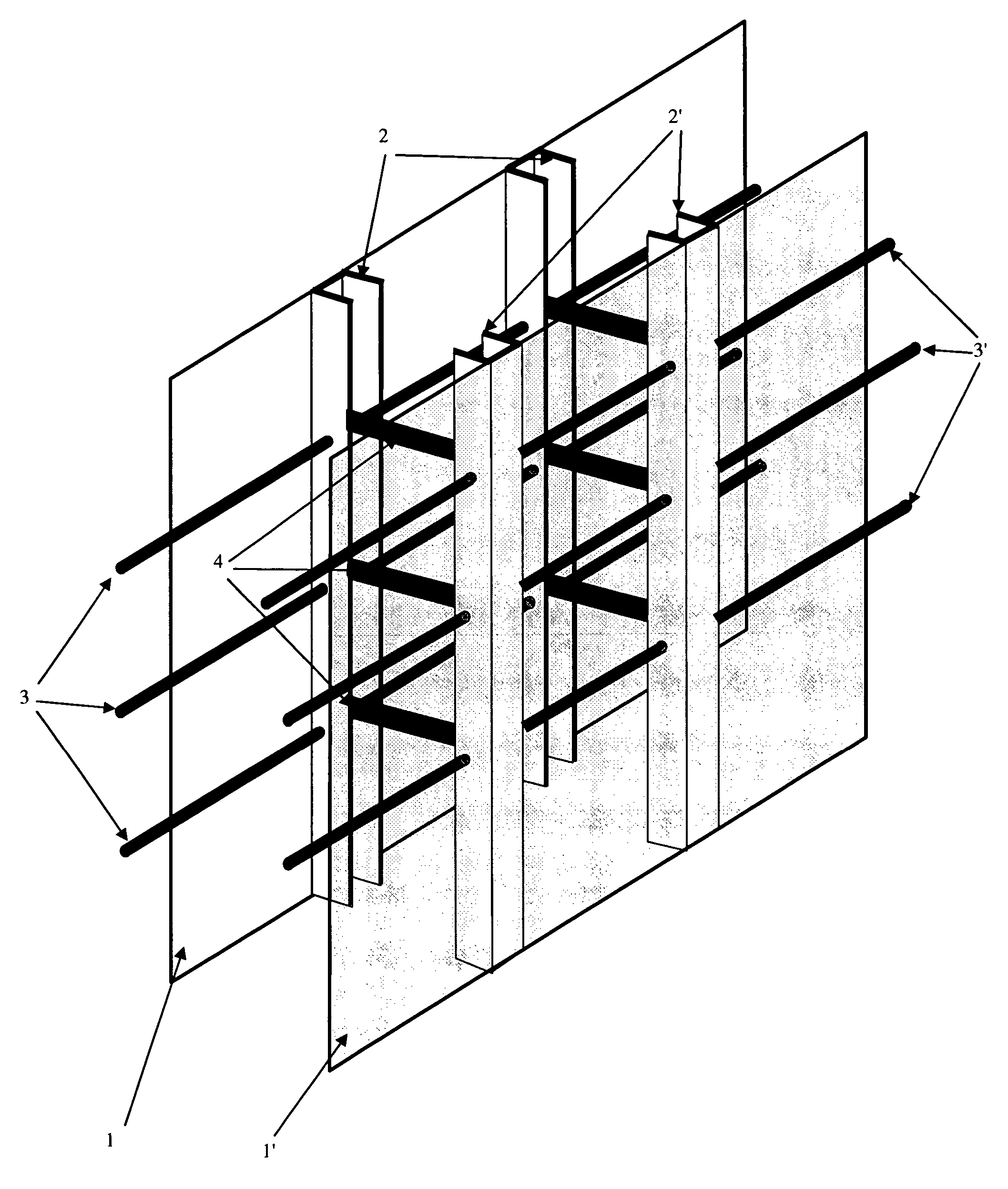
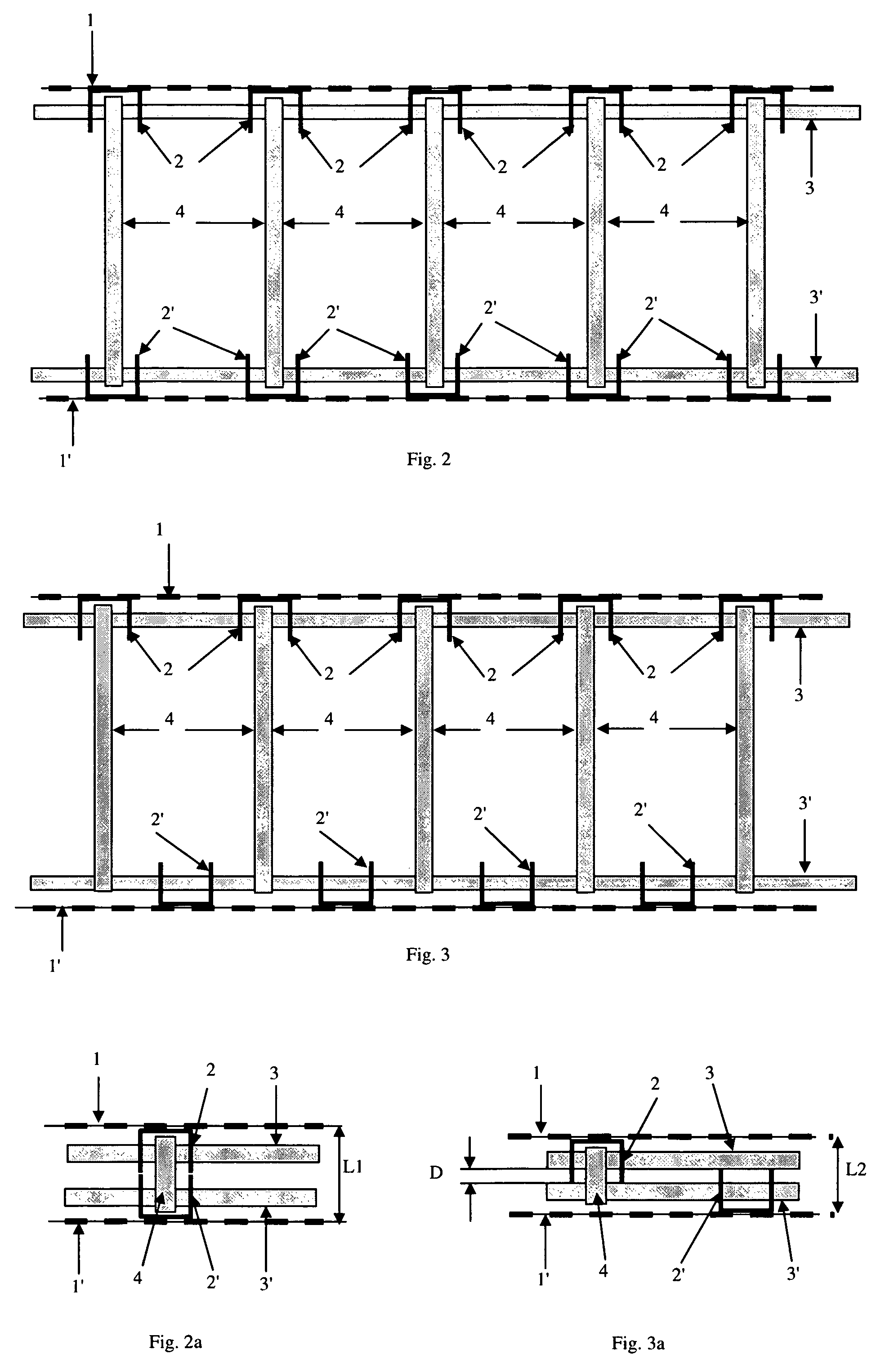
[0032]FIG. 1 shows a part of a formwork for a concrete wall including two parallel formwork walls placed one facing the other. Each wall is provided with U-shaped vertical bars whose aperture is directed in towards the formwork. They are spaced preferably at regular intervals on the entire length of the wall. These bars called stiffeners contribute to the stability of the formwork walls (1, 1′), which are generally made up of relatively flexible latticed metallic panels. The stiffeners are fixed to the mesh of the formwork walls by welding, by hooking on the lugs or by tying with metallic wire means.

[0033]The formwork walls include horizontal ribs distributed at more or less regular intervals on the height. These ribs are used to stiffen the walls in order to avoid their deformation under the push of the concrete, above all in the case where the intervals between the vertical stiffeners are large.

[0034]The mesh of the formwork walls has a size adapted to the passage of the finest pa...


PUM


Abstract

The aim of this invention is to increase the rigidity of the integrated formworks at the time of their installation, to facilitate the work of the civil engineers if order to determine easily the contribution of the horizontal frameworks and to reduce manufacturing costs. This aim is reached by a formwork including two parallel formwork walls placed one facing the other provided with shaped bars forming the vertical stiffeners and connected by at least one articulated connection device allowing the maintenance of the formwork walls either at a distance defining a space to receive a filler such as concrete, or folded for storage and transport. The connection device is characterized in that it includes a first rectilinear horizontal bar parallel to the first formwork wall and passing through the stiffeners of said first wall, a second rectilinear horizontal bar parallel to the second formwork wall and going through the stiffeners of said second wall, said second bar being situated facing the first bar, and a plurality of connection bars perpendicularly linking the two horizontal bars, said connection bars being articulated around said horizontal bars.

Description

FIELD OF THE INVENTION[0001]This invention has for an object a formwork for the manufacture of a concrete or concrete-like material wall. This formwork is constituted of two metallic formwork walls provided with vertical stiffeners and placed one facing the other. These formwork walls are linked by a connection device separating the walls by creating a space between them to be filled with material such as concrete.TECHNICAL BACKGROUND[0002]In order to guarantee the solidity of buildings' walls or of other concrete works, it is foreseen to have at its disposal an additional vertical framework inside the walls. A common technique consists in using this formwork system as a permanent or integrated formwork, that is to say, with a formwork which subsists as an integral part of the wall after having poured concrete on the inside.[0003]The documents EP0883719 and WO02 / 38878 describe a formwork comprising an outer wall and a backing wall, these walls, called formwork walls, include vertica...

Claims


Application Information

Patent Timeline
Patent Type & Authority Patents(United States)
IPC IPC(8): E04H12/18E04B2/00E04B9/00E06B3/54E04H9/00E04H6/00E04H5/00E04H3/00E04H1/00E04H12/00E04B2/86
CPCE04B2/8635E04B2/8658E04B2/86
Inventor MESSIQUA, PIERREMESSIQUA, REGIS
Owner POLYFINANCE COFFOR HLDG SA
Why Eureka
Try Eureka