Multiple elastomer layer progressing cavity stators

a technology of elastomer layer and stators, which is applied in the direction of machines/engines, rotary/oscillating piston pump components, liquid fuel engines, etc., can solve the problems of cracks, cavities, and other types of failure of the lobe, so as to improve the performance of the stator and reduce the associated tradeoffs , the effect of improving reliability

a technology of elastomer layer and stators, which is applied in the direction of machines/engines, rotary/oscillating piston pump components, liquid fuel engines, etc., can solve the problems of cracks, cavities, and other types of failure of the lobe, so as to improve the performance of the stator and reduce the associated tradeoffs , the effect of improving reliability

US7517202B2Inactive Publication Date: 2009-04-14SMITH INT INC

Image

  • Multiple elastomer layer progressing cavity stators
  • Multiple elastomer layer progressing cavity stators
  • Multiple elastomer layer progressing cavity stators

Examples


Embodiment Construction

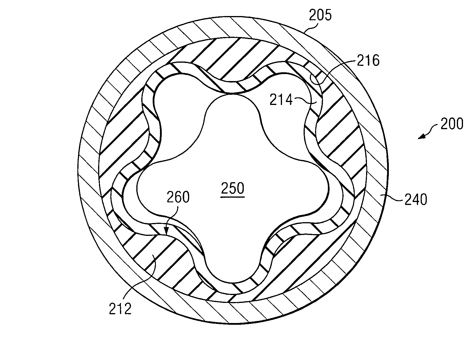
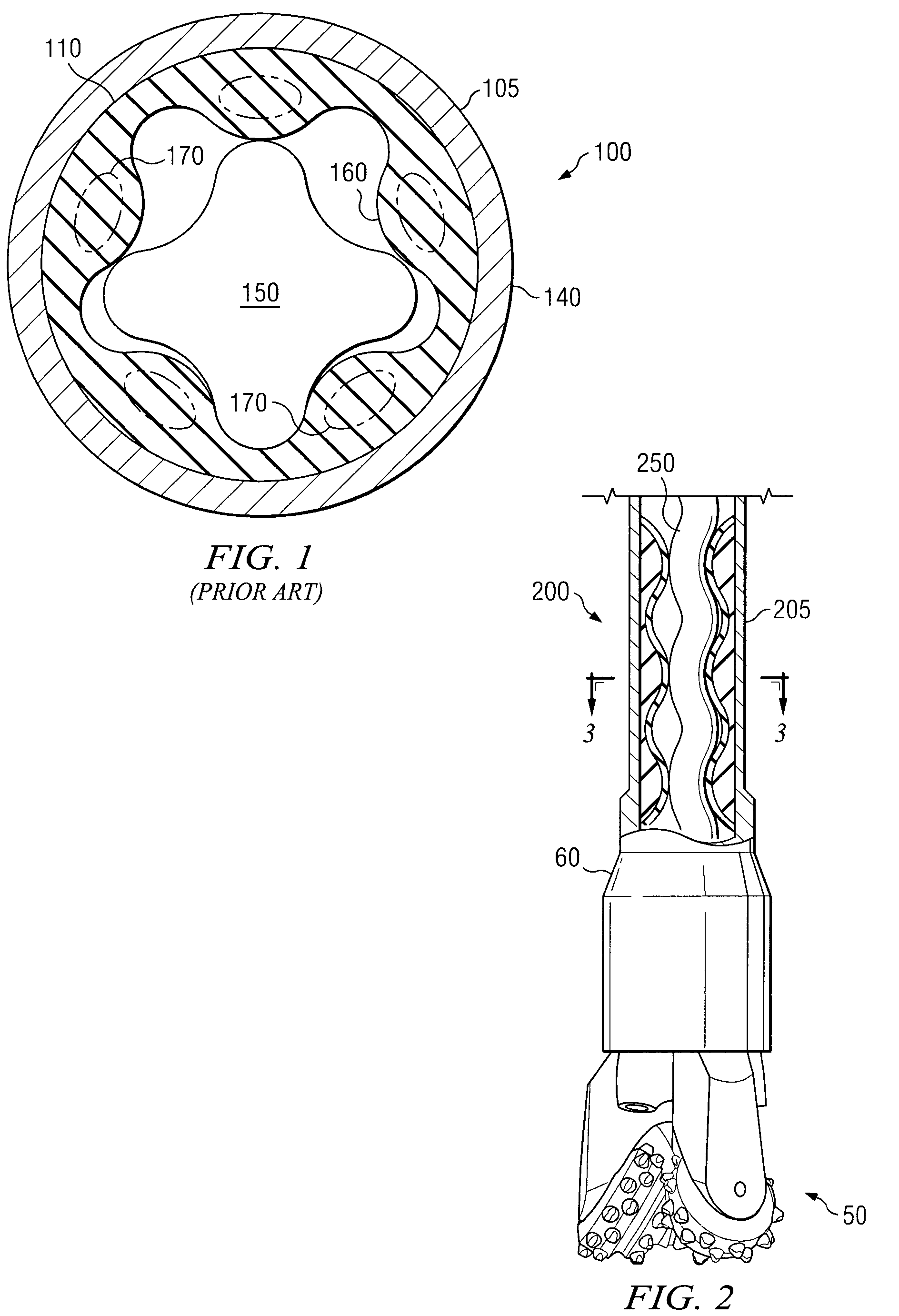
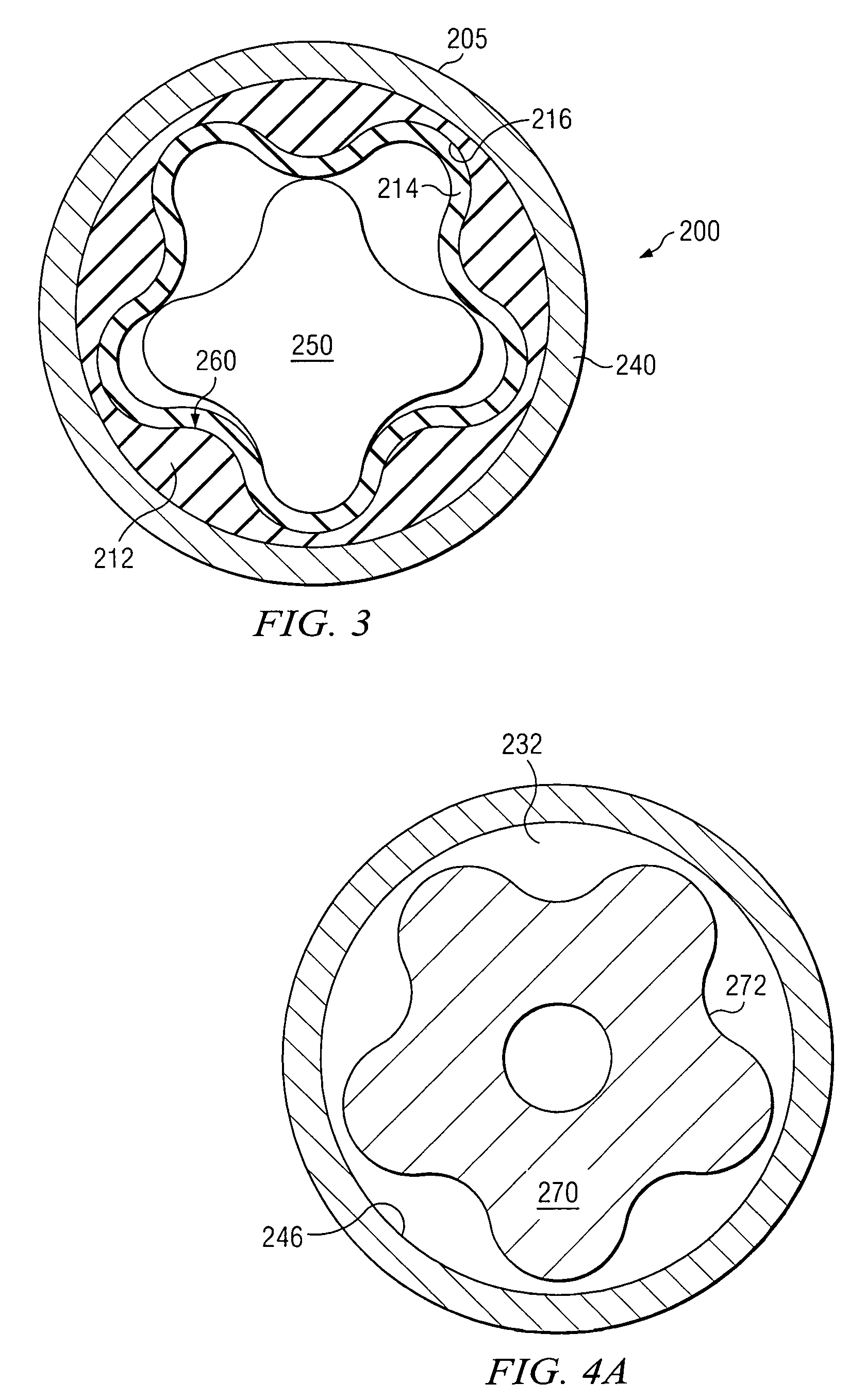
[0024]FIGS. 1, 3, 5, and 7 each depict circular cross-sections through Moineau style power sections in an exemplary 4 / 5 design. In such a design, the differing helical configurations on the rotor and the stator provide, in circular cross section, 4 lobes on the rotor and 5 lobes on the stator. It will be appreciated that this 4 / 5 design is depicted purely for illustrative purposes only, and that the present invention is in no way limited to any particular choice of helical configurations for the power section design.

[0025]FIG. 1 depicts a conventional Moineau style power section 100 in circular cross-section, in which stator 105 provides a helical cavity portion 110. In the embodiment of FIG. 1, helical cavity portion 110 is of an all-elastomer construction, including a single elastomer layer. Rotor 150 is deployed within stator 105. Stator 105 further comprises outer tube 140. Helical cavity portion 110 is deployed on the inside of outer tube 140, as is well known in the art.

[0026]...


PUM


Abstract

A progressing cavity stator and a method for fabricating such a stator are disclosed. The progressing cavity stator includes first and second elastomer layers fabricated from corresponding first and second elastomer materials. The first and second elastomer materials are selected to have at least one distinct material property. Exemplary embodiments of this invention may reduce tradeoffs associated with elastomer material selection and may further address the heat build up and subsequent elastomer breakdown in the lobes of prior art stators.

Description

RELATED APPLICATIONS[0001]None.FIELD OF THE INVENTION[0002]The present invention relates generally to positive displacement progressing cavity drilling motors, typically for downhole use. This invention more specifically relates to progressing cavity stators having multiple internal elastomer layers and a method for fabricating stators having multiple elastomer layers.BACKGROUND OF THE INVENTION[0003]Progressing cavity hydraulic motors and pumps (also known in the art as Moineau style motors and pumps) are conventional in subterranean drilling and artificial lift applications, such as for oil and / or gas exploration. Such progressing cavity motors make use of hydraulic power from drilling fluid to provide torque and rotary power, for example, to a drill bit assembly. The power section of a typical progressing cavity motor includes a helical rotor disposed within the helical cavity of a corresponding stator. When viewed in circular cross section, a typical stator shows a plurality of ...

Claims


Application Information

Patent Timeline
14 Apr 2009
Publication
US7517202B2
IPC
F01C1/10; F01C5/00
CPC
F04C2/1075; F04C13/008; F04C2230/20
Inventors
DELPASSAND, MAJID S.