Method for increasing a blade performance (variants)

a blade and variable technology, applied in the field of mechanical engineering, can solve the problems of ineffective present method, high energy expenditure, complicated design of the boundary layer control, etc., and achieve the effect of increasing the blade performance and reducing the energy expenditure for controlling

Inactive Publication Date: 2009-04-21
LNS WINDBLADE TECH LLC +1
View PDF11 Cites 9 Cited by
  • Summary
  • Abstract
  • Description
  • Claims
  • Application Information

AI Technical Summary

Benefits of technology

[0006]It is a technical problem to be solved by the present invention to increase a blade performance, including blades in an air supercharger or a propulsion device rotor, because of providing the without a break of flow of the air around blades produced in the form of a wing with a thick airfoil profile, and because of reducing the energy expenditure for controlling a boundary layer by means of the boundary layer suction from a blade surface on the opposite side with respect to the incoming air flow.
[0017]The analysis of the blade operation shows that, when the air flow passes around the blade airfoil profile, a flow with a positive pressure gradient is realized at the blade surface on the side of the incoming flow closer to the trailing edge of the blade, said positive pressure gradient flow preventing the air motion within a region of the boundary layer where velocities are relatively small. The result of such an action can be break of flow from the surface in the trailing edge of the blade and consequently significant increase in the aerodynamic resistance of the blade section at reduction in the lift force.
[0018]To improve aerodynamic characteristics of the blade section, it is possible to enhance a velocity of air that passes around the blade surface on the side of the incoming flow. One way to accelerate the air flow that passes around this wing surface is to suck the boundary layer which allows the flow to overcome the positive pressure gradients without break of flow at a curvilinear upper (in case of a helicopter rotor) surface of the blade.
[0019]Embodiment of the blades with the above-mentioned system of cavities—that include central bodies—and branch channels allows significant reduction in energy expenditure for suction of the boundary layer, and as a consequence, improvement in aerodynamic blade characteristics accompanied with increase in the lift force created by the blade. Further functionality concerning with energy expenditure reduction is accomplished due to limiting the longitudinal overflow of the sucked air along cavities and limiting the air flow along external surfaces of the blades.

Problems solved by technology

However, the present method is ineffective which is connected with large energy expenditure for blowing air in along the blade surface.
The disadvantage of the present method for increasing a rotor blade performance is that such a control of the boundary layer involves a complicated design and high energy expenditure for suction of the flow, which is associated with a large resistance of manifolds connecting the slotted holes to a low pressure source in the blade.

Method used


Image

  • Method for increasing a blade performance (variants)
  • Method for increasing a blade performance (variants)
  • Method for increasing a blade performance (variants)

Examples


Embodiment Construction

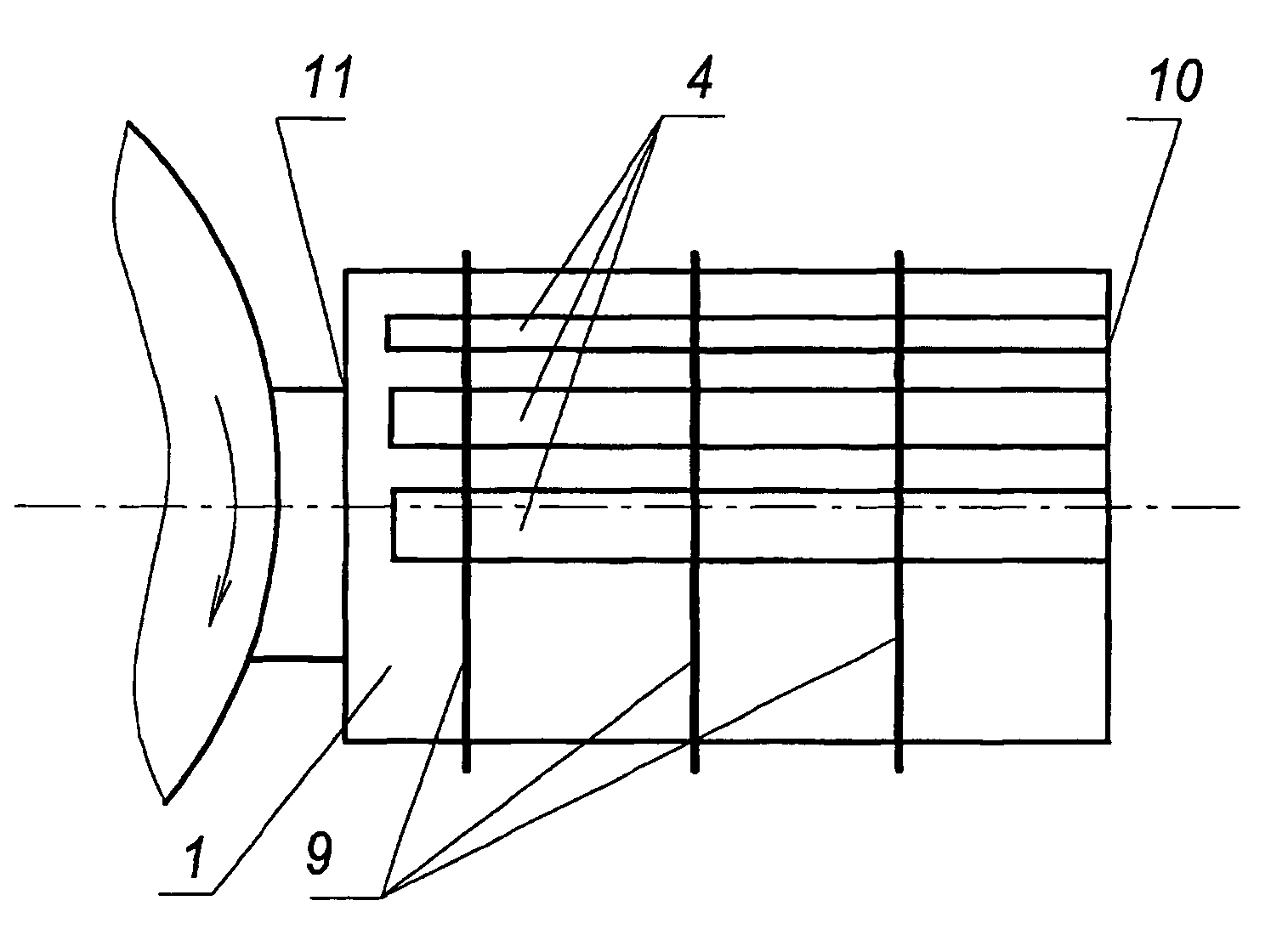
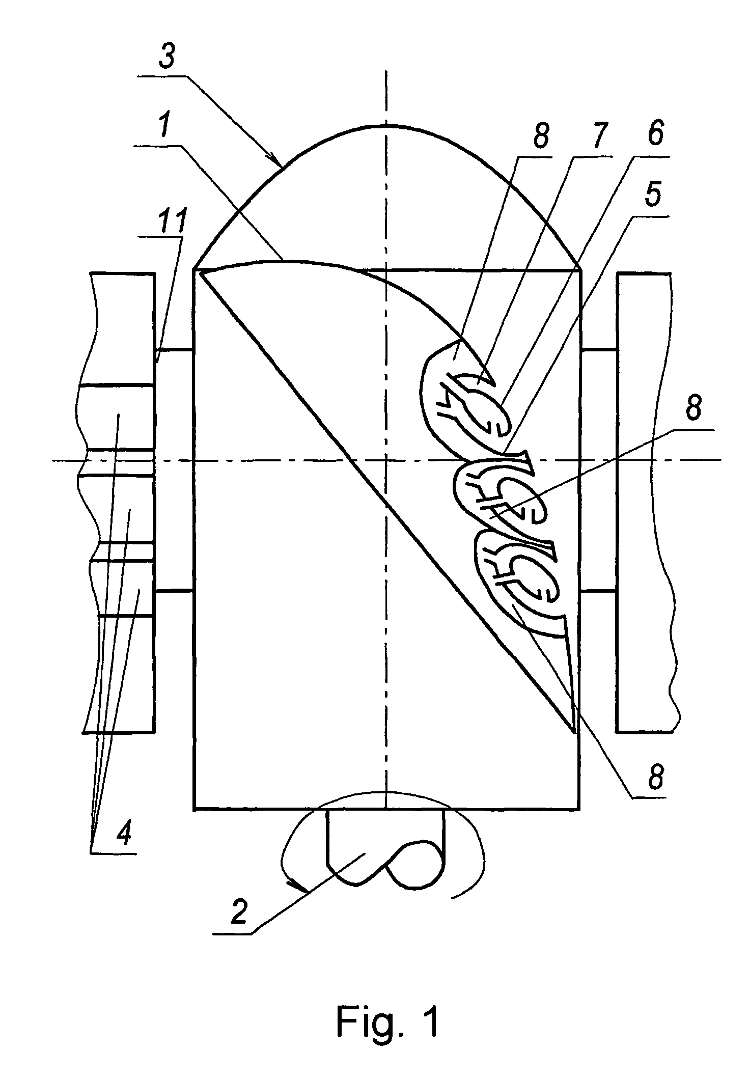
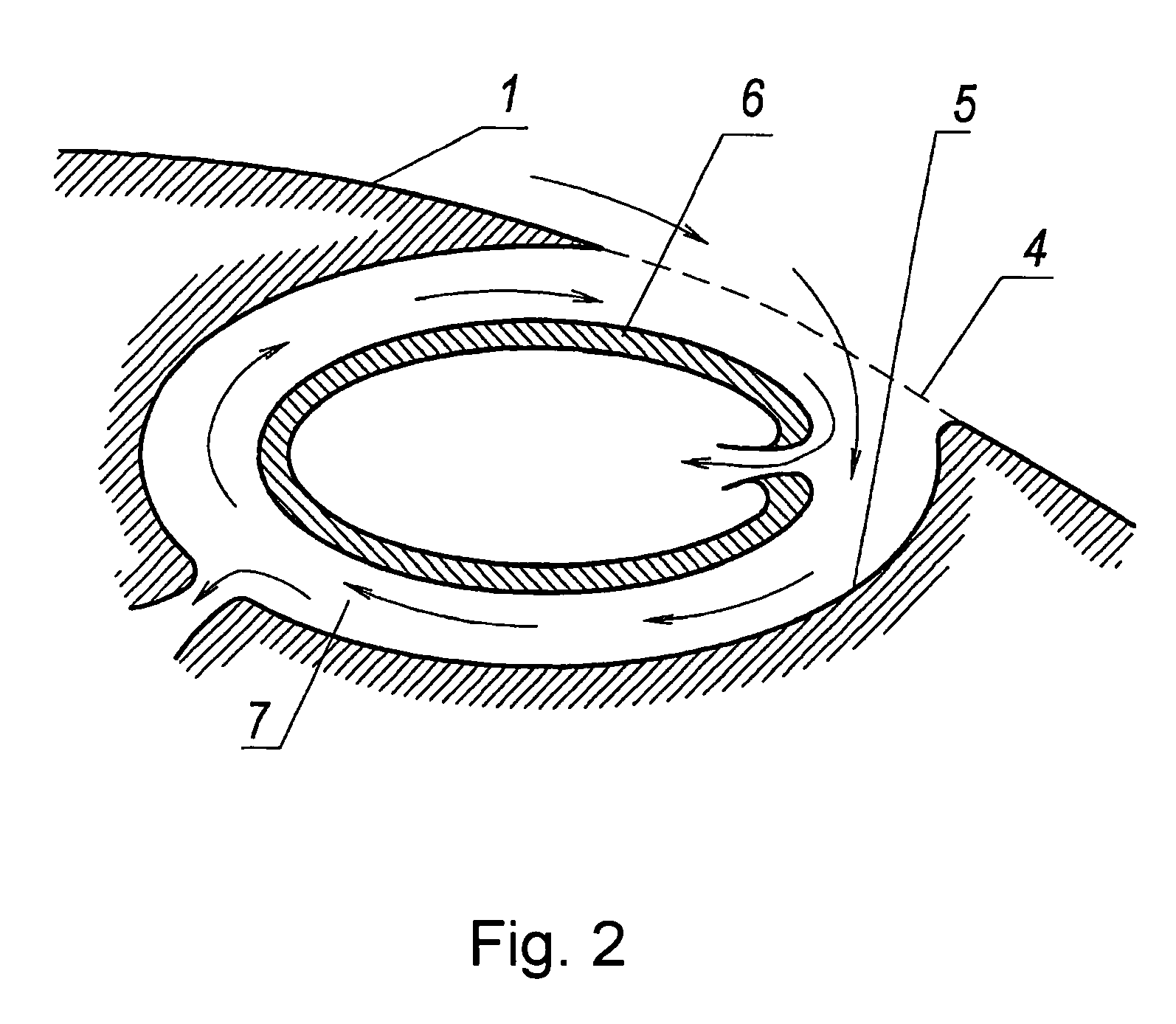
[0025]In realization of a method of operation, blades (or vanes of turbine or fan and etc.), that is the same in the present case) 1 are radially mounted around a shaft 2 of a rotor 3. A blade 1 is produced in the form of a wing with a thick airfoil profile, and a vortex system for controlling a boundary layer, comprising slotted holes 4 embodied along the blade, is provided on a surface of the blade 1—on a side opposite to an incoming air flow. Cavities 5 are embodied under said holes 4 along the latter, each cavity being provided (or not provided —depending upon an embodiment of the blade) with a central longitudinal hollow body 6 forming an annular channel 7 in each cavity to generate a vortex-like flow by the incoming air flow in said channel. Discharge of the sucked medium from the cavities 5 and the central bodies 6 is carried out by means of branch channels 8 that may be in communication with environment or a suction member. Partitions (not shown) that divide a cavity 5 into ...


PUM

PropertyMeasurementUnit
thickaaaaaaaaaa
air suctionaaaaaaaaaa
velocityaaaaaaaaaa

Abstract

The invention relates to machine building in particular to blade machines for air injection, in particular to fans and air blowers, and also to blades of different propulsion devices. The inventive method for increasing the blade (1) performance consists in producing a blade (1) in the form of a wing and in carrying out the boundary layer suction on the blade 1 surface on the opposite side with respect to the incoming air flow through a system of slotted holes (4). The blade (1) is provided with a thick airfoil profile. The air suction is carried out through the system of slotted holes (4) embodied along the blade (1) and into cavities (5) which are embodied under said holes (4) along the latter and each of which is provided with a central longitudinal hollow body arranged therein, said body forming an annular channel (7) in each cavities (5) in such a way that a vortex-like flow is generated by the incoming air flow in said channel. The air is sucked out from the cavities (5) and the central bodies (6) through branch channels (8). The latter are used to discharge air outside of the blade (1). The air flowing-off along the cavities (5) and along the blade 1 is limited within the cavities (5) by mounting partitions and on an external surface of the blade (1)—by mounting ribs (9). In another embodiment of the method, the cavity is embodied without the central body (6). As a result, the invention makes it possible to increase the blade performance.

Description

FIELD OF THE INVENTION[0001]The invention relates to mechanical engineering, in particular to blade machines for air injection, in particular to fans and air blowers, and also to blades of different propulsion devices (in helicopters, airplanes, etc.).BACKGROUND OF THE INVENTION[0002]Known is a method for increasing a blade performance, consisting in producing blades in the form of a wing and mounting them around a rotor shaft while carrying out the suction of air in a blade shank (foot) region (blade section adjacent to the rotor shaft), draining-off said air to a leading edge zone of the blade, followed by blowing the air out along an upper surface of the blade (see U.S. Pat. No. 6,203,269, IPC F01D 5 / 14, Mar. 20, 2001).[0003]The present method allows reduction in separation of the air flow at the upper surface of the blade due to increase of the air flow velocity. However, the present method is ineffective which is connected with large energy expenditure for blowing air in along ...

Claims


Application Information

Patent Timeline
Patent Type & Authority Patents(United States)
IPC IPC(8): B64C11/16B64C11/18B64C21/06F04D29/30F04D29/38F04D29/68
CPCB64C11/18B64C21/06F04D29/681F04D29/384Y10T29/49327Y02T50/166F04D29/682Y02T50/10
Inventor SCHUKIN, ILYA LVOVICHCHTCHOUKINE, ANDREI LEVZELVINSKY, SEMEN MIKHAILOVICHLIPNITSKY, JURY MIKHAILOVICH
Owner LNS WINDBLADE TECH LLC
Why Eureka
Try Eureka