Laser ionization mass spectroscope

a laser ionization and mass spectrometer technology, applied in the field of photoaccumulation type laser ionization mass spectrometer, can solve the problems of insufficient ionization of laser ionization, etc., to achieve efficient identification and quantification, and enhance multi-photon ionization

Inactive Publication Date: 2009-04-21
IDX TECH
View PDF6 Cites 15 Cited by
  • Summary
  • Abstract
  • Description
  • Claims
  • Application Information

AI Technical Summary

Benefits of technology

[0015]The object of the present invention is to provide an analyzer via supersonic jet resonance enhanced multi-photon ionization which enables efficient identification and quantification of extremely small amount of substances contained in a carrier gas.Means for Solving the Technical Problems

Problems solved by technology

In the case of this system, the biggest technical problem is at what position of a distance from the nozzle of the high speed pulse valve the laser beam should be irradiated with the optimum effect to the carrier gas flow.
Although it has been possible to detect dioxins through irradiation of laser beam of the above-described pulse width to sample molecules, there has been no report of success in their quantification and identification.
Even in the case of this system, however, there has been no report of success in identification and quantification.
These substances are in many cases hygroscopic.
When these substances are used for the high speed pulse valve, there is a problem of adsorption to metallic walls.
It is not allowed to raise the temperature higher since the result does not suffice the flow condition of the gas ejected from the nozzle.
This condition is not sufficed since the vacuum sealing element of the pulse valve undergoes thermal expansion, the lift of the valve body of the electromagnetic valve is constant, no sufficient gap can be left between the sealing element and the valve body and, as a consequence, the amount of carrier gas flowing into the nozzle decreases.

Method used


Image

  • Laser ionization mass spectroscope
  • Laser ionization mass spectroscope
  • Laser ionization mass spectroscope

Examples


Embodiment Construction

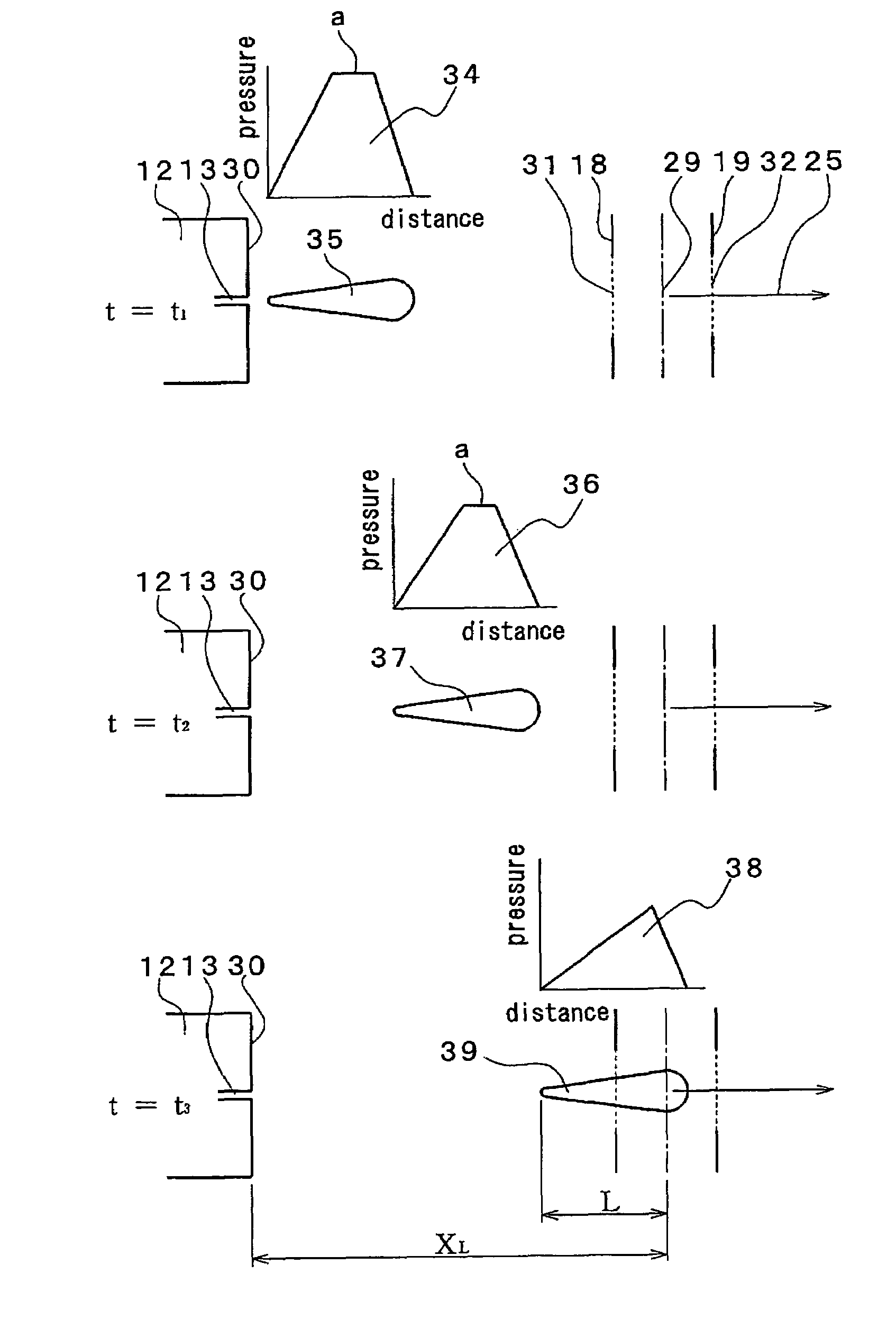
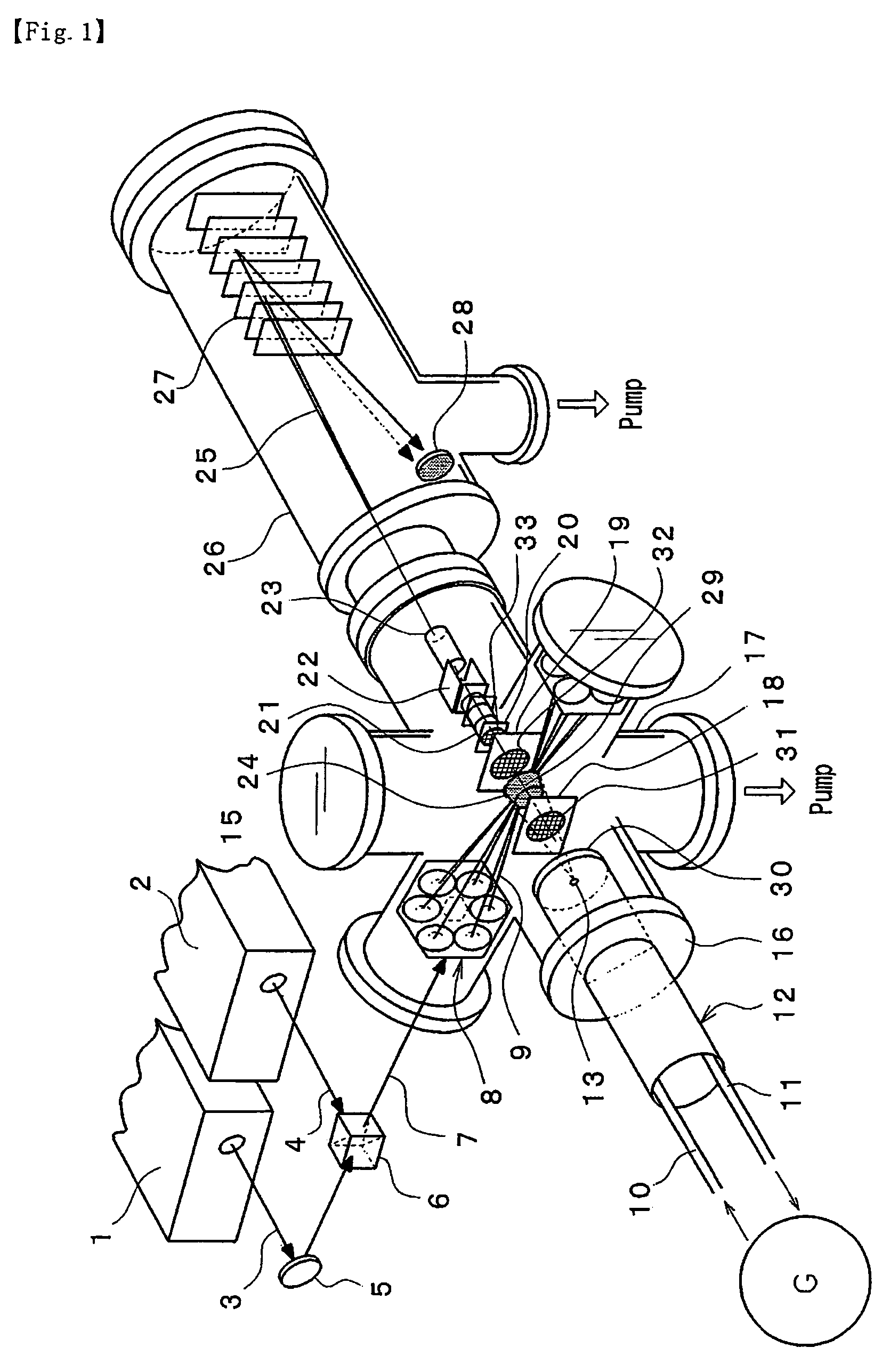
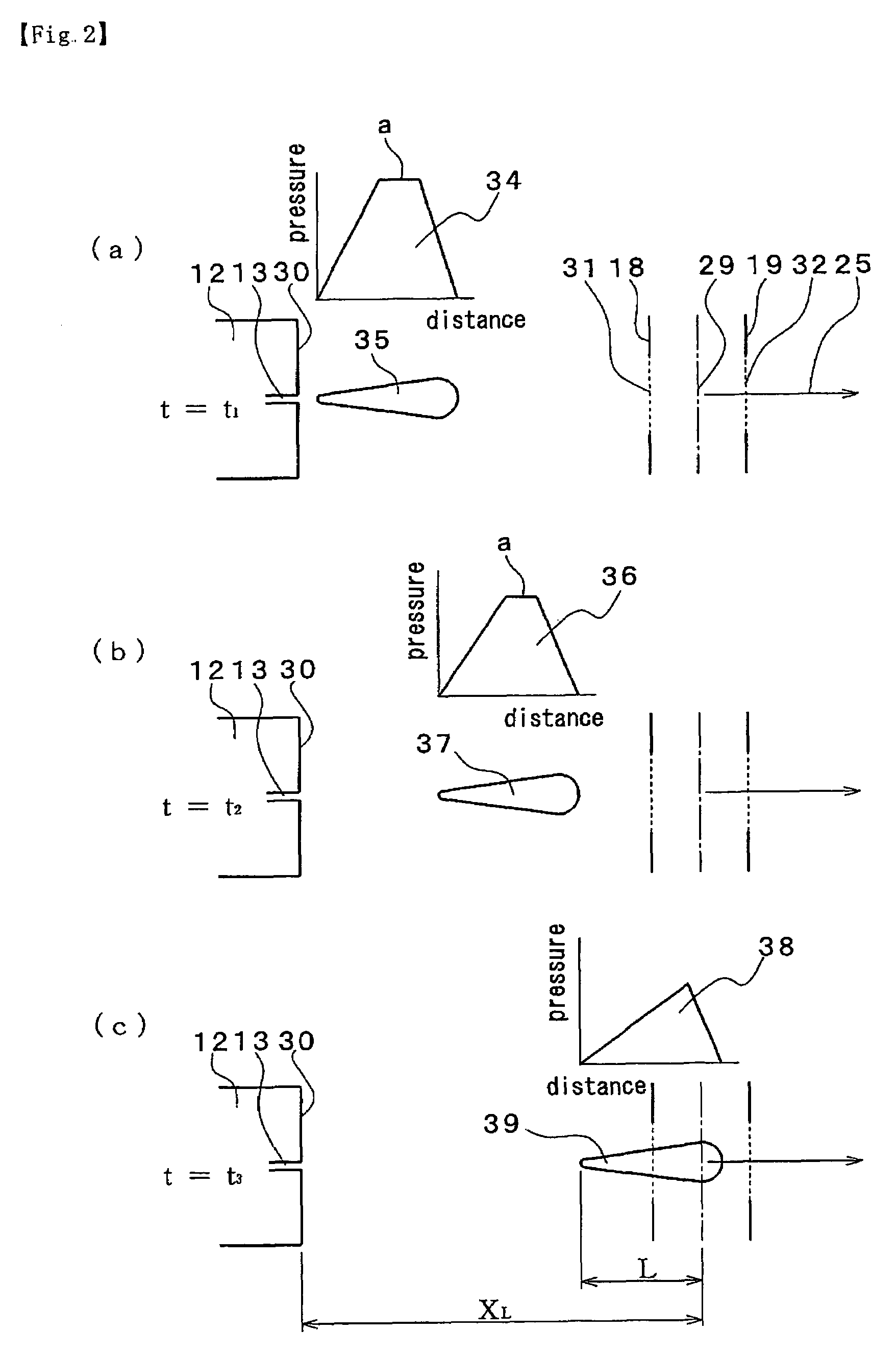
[0039]In the system shown in FIG. 1, carrier gas containing sample molecules is fed from a gas supply source G. The carrier gas passes through a gas flow-in tube 10 and is passed to a gas retention space 52 (FIG. 4) of a pulsed gas ejecting device 12. A part of the carrier gas is ejected in the form of a pulsed gas 24 into a vacuum vessel 17 and the remainder is returned to the gas supply source G via a heated gas flow-out tube 11.

[0040]The pulsed gas 24 ejected into the vacuum vessel 17 travels past a mesh 31 of a repeller electrode 18 and is subjected to irradiation of laser flux 9 at a position distant over a prescribed distance from an outer surface 30 of the pulsed gas ejecting device 12. Sample molecule ions 29 are generated by selective photo-reaction.

[0041]The generated sample molecule ions 29 are extracted in the direction towards a reflectron flight time type mass spectrometer 26 by the action of an electric field formed between the repeller and extraction electrodes 18, 1...


PUM

PropertyMeasurementUnit
diameteraaaaaaaaaa
temperatureaaaaaaaaaa

Abstract

The invention provides an ultra-sonic jet multi-photon resonance ionization type mass analyzing device.The laser beam ionization mass analyzing device includes a pulsed gas ejecting device 12 for ejecting in pulse mode carrier gas containing sample molecules into a vacuum vessel 17, a laser beam irradiation system for irradiating laser beam for selective photo-reaction of sample molecules in said pulsed gas, repeller and extraction electrodes 18 and 19 generating an electric field for extraction of sample molecular ions generated by the photo reaction and a mass analyzing device 26 for mass analysis of extracted sample molecular ions. The laser beam irradiation system is set to irradiate laser beam to sample molecules near a position whereat a pressure time distribution of pulsed gas translating in the vacuum vessel 17 transitions from a flat-top pressure distribution to a triangular pressure distribution.

Description

[0001]This is a nationalization of PCT / JP2005 / 004521 filed 15 Mar. 2005 and published in Japanese.TECHNICAL FIELD OF THE INVENTION[0002]The present invention relates to a photo-accumulation type laser ionization mass spectrometer in which carrier gas containing sample molecules such as dioxins is ejected in pulse mode from a nozzle of a ejecting device provided with a high speed short duration pulse valve into a vacuum vessel, carrier gas is irradiated to said carrier gas flow for selective ionization of sample molecules and the ionized sample molecules are detected and analyzed by a mass spectrometer.BACKGROUND ARTS[0003]For these years, an analyzer based on supersonic jet resonance enhanced multi-photon ionization process (Jet-REMPI method) has been proposed which enables direct and on-line analysis of dioxins. In the process, carrier gas containing sample molecules such as dioxins is ejected in pulse mode from an ejecting device provided with a high speed short duration pulse val...

Claims


Application Information

Patent Timeline
Patent Type & Authority Patents(United States)
IPC IPC(8): H01J49/00B01D59/44G01N1/00G01N27/64H01J49/16H01J49/40
CPCH01J49/0422H01J49/162H01J49/40
Inventor KIRIHARA, NAOTOSHIKITADA, NORIFUMITAKAHASHI, KENJIYOSHIDA, HARUAKITANAKA, MIZUHOSUZUKI, YASUO
Owner IDX TECH
Why Eureka
Try Eureka