Magnetic detecting device and material identifying device

a magnetic detection and material technology, applied in the direction of magnetic property measurement, material magnetic variables, instruments, etc., can solve the problems of inability to apply methods, objects that are not being conveyed, and inability to obtain measurements instantaneously, so as to prevent a magnetic field induced, reduce the effect of noise components, and improve repeatability

Inactive Publication Date: 2009-04-28
UNIV OKAYAMA
View PDF13 Cites 29 Cited by
  • Summary
  • Abstract
  • Description
  • Claims
  • Application Information

AI Technical Summary

Benefits of technology

[0028]According to the first aspect of the present invention, it is possible to detect, by means of a lock-in amplifier circuit, an output from the measurement circuit for the magnetic sensor into two signals having the same frequency as that of the apply coil and phases different by 90 degrees from each other. Thus, the output can be separated into two parts, a magnetic response from the ferromagnetism and a response from an eddy current. Since an induced electromotive force V in an electrical conductor generated by an alternate magnetic field is proportional to a time rate of change of a magnetic flux Φ(dΦ / dt), V can be represented as follows, where Φ=Φ0 exp(iωt) (i: an imaginary unit):V=−iωΦ0 exp[iωt]=ωΦ0 exp[i(ωt−π2)]Thus, the phase of an eddy current I (=V / R, R: resistance) induced by the above described induced electromotive force V is shifted by 90 degrees (π / 2) from the above described alternate magnetic field. In other words, the intensity of the magnetic field H generated at the position of the magnetic sensor by the above described current is represented as H=I / 2r where the eddy radius of the eddy current is r. Thus, the phase of a magnetic response from the electrical conductor is shifted by 90 degrees because of the phase shift of the eddy current. Accordingly, the above described magnetic response containing magnetic signals generated in different ways as described above can be separated into two signals having phases different by 90 degrees from each other. Thus, various information can be obtained from the magnetic response characteristics of the above described test object.
[0029]Further, while the frequency of the alternate magnetic field was fixed in the prior art, the frequency may be variable in the present invention. Even if the test object contains a complex of a magnetic material and a nonmagnetic material, the complex object can be identified by measuring a change in the response characteristics in response to a change in frequency. Thus, it is not necessary to convey the test object to measure a time change in phase, and material identification of the test object in the magnetic field can be made in a moment of time. In addition, it is possible to confine magnetic changes to be detected to those caused by a magnetic response from the test object by detecting the output from the measurement circuit for the magnetic sensor using the same frequency as that of the apply coil.
[0030]Further, the magnetic sensor can be used even in the case where the signal of magnetic response characteristics is weak and of low frequency, because the above described magnetic sensor is placed near the test object. Since the magnetic sensor responds to a direct magnetic field, an environmental magnetic field such as the terrestrial magnetism may cause a noise louder than the signal. However, the noise component can be effectively removed by providing a cancel coil at a position adjacent to the magnetic sensor. Although the applied alternate magnetic field may cause a noise at the position of the magnetic sensor, the above described noise component can be removed in a dramatically improved manner by providing a cancel coil for the alternate magnetic field.
[0031]When measuring magnetic response characteristics of the test object, the magnetic change varies depending on the distance between the apply coil and the test object and the distance between the magnetic sensor and the test object. According to the second aspect of the present invention, detection can be made with higher repeatability because a distance measurement means for measuring the distance between the apply coil and the magnetic sensor is provided. Further, since distance information can be obtained as well as magnetic response information, there is no need to continuously measure the phase change of the magnetic signal, and the structure materials contained in the test object can be identified in a moment of time based on the above described magnetic response.
[0032]According to the third aspect of the present invention, it is possible to prevent a magnetic field induced by the cancel coil from being applied to the test object, by making the area of said cancel coil small so as not to influence the magnetic detection with the use of said magnetic sensor. A preferable ratio of coil areas, which can be obtained by dividing the area of the cancel coil by the area of the apply coil, is a tenth or less. In order to increase the rate of decay of the magnetic field as a function of the distance from the cancel coil, a more preferable ratio of coil areas is a fiftieth. Most appropriately, the rate of coil areas is a hundredth or less, with which the rate of decay of the magnetic field as a function of the distance from the cancel coil increases dramatically, making the influence of the cancel coil upon the test object negligible.
[0033]According to the fourth aspect of the present invention, since a composite magnetic field of a plurality of frequencies is generated, and an output of the magnetic sensor is phase-detected using a plurality of frequencies instead of changing the frequency of the applied magnetic field, magnetic responses of the test object for two frequencies can be measured simultaneously without switching between the frequencies. Therefore, measurement of the frequency characteristics of a magnetic response may be speeded up dramatically.

Problems solved by technology

With a method of measuring a phase change as a means for analyzing a complex test object such as meat containing a misplaced metal piece, results of measurement cannot be obtained instantaneously because there is a need for measuring the complex test object flowing on a belt conveyor for a certain length of time to obtain a time change.
As a result, this method cannot be applied, for example, to objects that are not being conveyed.
Further, there is a problem in the method for detecting a dangerous article by magnetizing ferromagnetic material such as iron that materials which are not supposed to be detected are also magnetized.
However, leaving out of consideration response characteristics for frequency changes in the applied magnetic field, an analysis cannot be made, for example, of a complex object containing magnetic and nonmagnetic materials.
However, there is a problem at issue of effects of high frequency magnetic fields being applied to a human body.
Although the effects of high frequency magnetic fields have not yet been quantified, there has been found a negative impact, for example, of heat generated with an eddy current in a human body induced by a high frequency magnetic field.

Method used


Image

  • Magnetic detecting device and material identifying device
  • Magnetic detecting device and material identifying device
  • Magnetic detecting device and material identifying device

Examples


embodiment 1

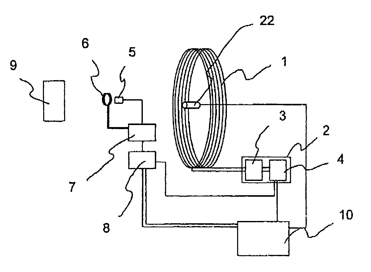
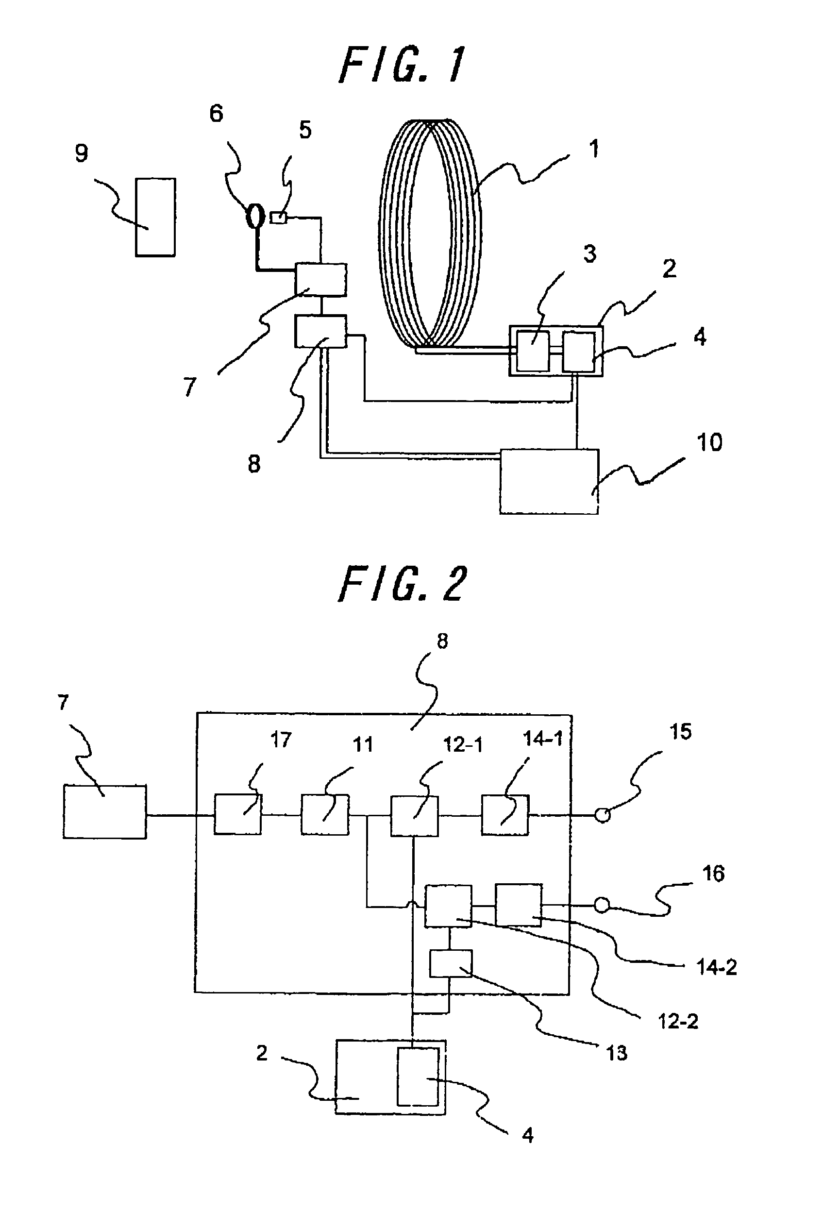
[0084]FIG. 1 is a schematic diagram showing a basic configuration of a magnetic detecting device according to the present invention. A magnetic field is applied by an apply coil 1 in order to measure a magnetic response of a test object 9. The frequency of the applied magnetic field can be changed by a power source 2 for the apply coil with the use of a signal sender 4. The generated signal drives a current source 3 to apply an alternate current to the apply coil 1. A change in the magnetic field induced by the test object 9 is detected by means of a magnetic sensor 5 comprising a magnetoresistance element. As a matter of course, any one of a magnetic impedance effect sensor, a flux gate, a superconducting quantum interference device can also be used instead. Environmental magnetic noises including the terrestrial magnetism is also input to the magnetic sensor 5, as well as the magnetic field from the test object 9. Not only that, the applied magnetic field is also applied to the ma...

embodiment 2

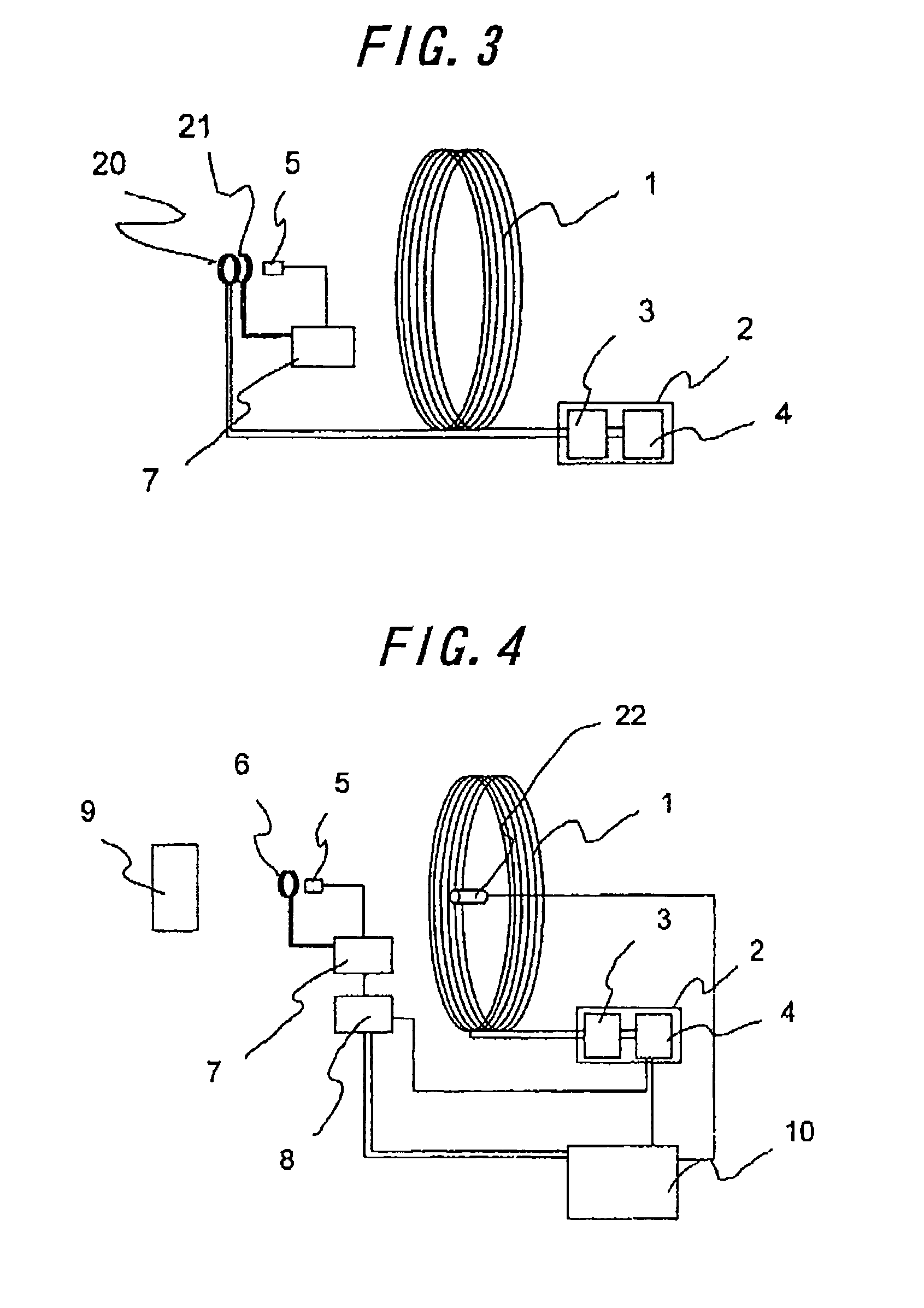
[0087]FIG. 3 is a schematic diagram showing a configuration of a coil of a magnetic detecting device according to a second embodiment of the present invention. The second embodiment relates to the magnetic detecting device according to the first embodiment, wherein the cancel coil 6 is separated into an apply coil magnetic field cancel coil 20 and a direct magnetic field cancel coil 21, and the apply coil magnetic field cancel coil 20 is connected to the power source 2 for the apply coil with the serially connected apply coil 1. Because the apply coil magnetic field cancel coil 20 and the apply coil 1 are connected in series, magnetic fields generated by the two coils have the same frequency. Consequently, adjustment is not required for the purpose of cancellation.

embodiment 3

[0088]FIG. 4 is a schematic diagram showing a basic configuration of a magnetic detecting device according to a third embodiment of the present invention. In the third embodiment there is provided a distance measurement means 22 for determining positions of the test object 9 and the apply coil 1. The distance measurement means 22 may be placed anywhere, either near the apply coil 1 or the magnetic sensor 5, provided that relative distances between the distance measurement means 22 and both the apply coil 1 and the magnetic sensor 5 are known. A magnetic response from the test object 9 for the applied magnetic field varies according to the distance from the apply coil 1, and the intensity of the signal differs greatly according to the distance from the magnetic sensor 5 for detecting the magnetic response. Thus, measurement can be carried out with higher repeatability by providing the distance measurement means 22.

[0089]FIG. 5 is a diagram showing a correspondence between the applied...


PUM


Abstract

The present invention discloses a magnetic detecting device comprising an apply coil 1 for generating an alternate magnetic field of variable frequency and a power source 2 for the apply coil; a magnetic sensor 5 for detecting a change in the magnetic field induced by a test object 9 placed at a distance from a surface of said apply coil and toward said test object, said magnetic sensor being provided with a cancel coil 6 for canceling a magnetic field generated at the position of the magnetic sensor by a direct magnetic field and / or said apply coil; a measurement circuit 7 for the magnetic sensor for measuring a detection signal of said magnetic sensor; a lock-in amplifier circuit 8 for detecting an output of said measurement circuit for the magnetic sensor into two signals having the same frequency as that of said apply coil and phases different from each other by 90 degrees; and an analysis means 10 for analyzing a phase change of the output of said magnetic sensor 5 using an output signal from said lock-in amplifier circuit 8.

Description

TECHNICAL FIELD[0001]The present invention relates to a device for applying an alternate magnetic field to a test object and detecting response characteristics thereof using a magnetic sensor.RELATED ART[0002]A metal detector is known as a device for applying an alternate magnetic field to examine the response characteristics. The metal detector comprises a search coil that generates an alternate magnetic field to generate an eddy current on a metal surface of the test object, which in turn generates a magnetic field repulsive to the applied magnetic field. Since this magnetic field changes an electromotive force in response to changes in the magnetic flux penetrating through the search coil, as may be represented using Faraday's law of electromagnetic induction, existence of metal can be detected by measuring the changes in a signal. Also known are methods of nondestrucive inspection such as a method for inspecting a defect in a steel pipe or a wire rope by generating an eddy curre...

Claims


Application Information

Patent Timeline
Patent Type & Authority Patents(United States)
IPC IPC(8): G01R33/12
CPCG01N27/72G01V3/104
Inventor TSUKADA, KEIJIKIWA, TOSHIHIKO
Owner UNIV OKAYAMA
Why Eureka
Try Eureka