
Method for efficient nonsynchronous LNG production

a non-synchronous, lng-based technology, applied in the direction of electric generator control, machines/engines, lighting and heating apparatus, etc., can solve the problems of significant problems for users connected to the electrical system, speed variation in power generation is not allowed, and significant problems for electrical users, so as to achieve maximum efficiency and reduce harmonic distortion

Active Publication Date: 2009-05-05
EXXONMOBIL UPSTREAM RES CO
View PDF16 Cites 33 Cited by
  • Summary
  • Abstract
  • Description
  • Claims
  • Application Information

AI Technical Summary

Benefits of technology

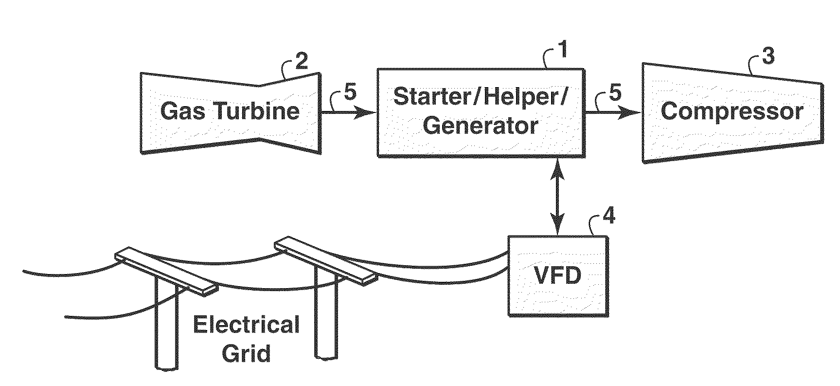
[0013]The invention is a drive system for a refrigeration compressor such as those used in natural gas liquefaction plants, comprising in one embodiment a gas turbine to provide primary power to run the compressor, an electric starter / helper motor / generator with drive-through capability positioned between the turbine and compressor on a common drive shaft, and a frequency converter electrically connected between the electric motor / generator and the electrical power grid. The frequency converter conditions the AC frequency both from the grid for smoother startup and nonsynchronous helper duty as well as to the grid so that excess turbine mechanical power can be converted to electrical power by the generator and supplied to the grid at the grid frequency, thus permitting the turbine speed to be dictated by throughput needs. In some embodiments, the frequency converter is a VFD with pulse-width modulation circuitry to reduce harmonic distortion in the output of the frequency converter. The invention is particularly suited for natural gas liquefaction plants where it is desirable to run the gas turbine at its maximum power for maximum efficiency and also to be able to vary the compressor rotational speed for throughput control, notwithstanding varying ambient temperature conditions which affect gas turbine output power.

Problems solved by technology

Speed variation in power generation is not allowed because of the precise requirement of 50 Hz or 60 Hz power.
Any deviation from 3000 rpm or 3600 rpm for 50 Hz and 60 Hz power, respectively, will result in significant problems for electrical users.
Generating electrical power at 51.7 Hz causes significant problems for users connected to the electrical system.
Operating a gas turbine at lower fuel rates will significantly reduce its efficiency and increase its emissions.
On the other hand, starting a gas turbine that is used as a compressor driver is much more demanding compared to starting a gas turbine driving an electrical generator.
Therefore, LNG production will tend to decline in the warmer months, and increase in colder months.
During such times, the practice has been to reduce the fuel flow rate to the gas turbine enough to eliminate excess power production (maintaining rotational speed) and accepting non-optimum gas turbine operating efficiency.
However, Kikkawa concludes that such increased use of the frequency converter, an expensive device, would necessitate having a spare frequency converter.
Kikkawa's method allows the gas turbine to be operated at its most efficient, but provides no throughput control, i.e., the gas turbines in his arrangement can operate at maximum power at synchronous speed but not maximum power at any other speed.
Furthermore, Kikkawa makes no allowance for maintaining stability during transient periods of compressor string operation.
The electrical connection between the propane and mixed refrigerant compression strings has its mechanical equivalent in a rigid coupling, making stable operation more difficult to control.

Method used


Image

  • Method for efficient nonsynchronous LNG production
  • Method for efficient nonsynchronous LNG production

Examples


Embodiment Construction

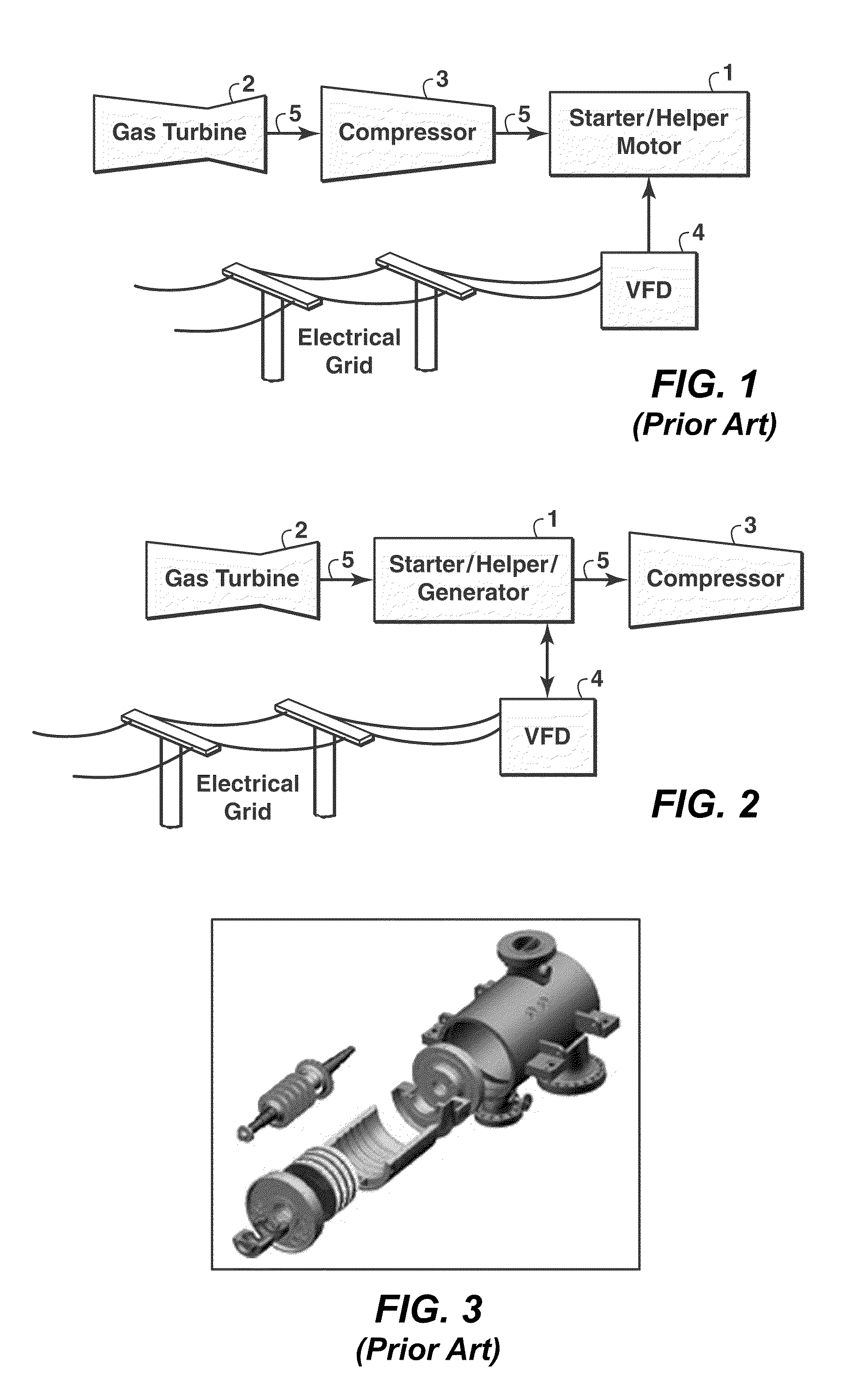
[0015]The present invention is a non-synchronous drive system for a refrigeration compressor such as is used in a natural gas liquefaction plant. FIG. 2 illustrates the configuration of the system of equipment in the present invention. The primary drive power is supplied by a gas turbine 2, sized to be capable of driving the refrigeration compressor (or compressors) 3 and producing excess mechanical power under the more favorable ambient temperature conditions that can be expected. The system includes an electrical starter motor / generator 1. This motor, regulated by a frequency converter 4 such as a VFD, starts the compression string from rest, and supplies additional torque in the helper mode as needed to compensate for warm weather decrease in turbine power output. Operating in generator mode, the motor converts excess mechanical power to electrical power. The compressor speed is dictated by plant LNG-throughput needs. The VFD is used not only for startup and helper duty, but also...


PUM


Abstract

A drive system for a refrigeration compressor such as is used in a natural gas liquefaction plant, allowing the desired compressor speed and maximum turbine efficiency to be maintained throughout varying ambient temperature conditions. A gas turbine is used with an electric starter motor with drive-through capability located on a common drive shaft between the turbine and the compressor. A variable frequency drive (VFD) is connected between the electrical power grid and the electric motor for smooth startups, but also to allow excess turbine mechanical power to be converted to electrical power by the motor operating as a generator, and delivered to the grid at the grid frequency. Pulse width modulation technology may be used to reduce harmonic distortion in the VFD's output. The starter motor also functions as a helper motor when the turbine output is insufficient to drive the compressor at the rotational speed needed to meet throughput requirements.

Description

CROSS REFERENCE TO RELATED APPLICATIONS[0001]This application is the National Stage of International Application No. PCT / US04 / 30669, filed 20 Sep. 2004, which claims the benefit of U.S. Provisional Patent Application No. 60 / 517,955, filed 6 Nov., 2003.FIELD OF THE INVENTION[0002]The present invention relates generally to the subject of natural gas liquefaction plants and, more particularly, to LNG (liquefied natural gas) plants that are powered by gas turbines. Specifically, the invention is a method of operating an LNG refrigeration compressor and associated starter / helper motor that allows the gas turbine to operate continually at its most efficient (maximum power) rating yet also allows for throughput control via variation in the rotational frequency of the compressor, notwithstanding ambient temperature variations.BACKGROUND OF THE INVENTION[0003]LNG or Liquefied Natural Gas results from a process in which natural gas is cooled until it becomes a liquid. Liquefying natural gas a...

Claims


Application Information

Patent Timeline
Patent Type & Authority Patents(United States)
IPC IPC(8): F25J3/00F01D15/10F01K25/02F02C1/04F02C6/00F25B1/00F25B49/00F25J1/00F01D15/00F02C7/268F25JF25J1/02
CPCF01D15/005F01D15/10F02C7/268F04D27/0292F25J1/0022F25J1/0283F25J1/0287F25J1/0298F25B2500/26F25J2280/10F05D2220/76F04D25/04F25J3/00F25B1/00
Inventor RASMUSSEN, PETER C.WRIGHT, STEPHENWALTER, JOHN D.
Owner EXXONMOBIL UPSTREAM RES CO
Learn More