Power supply and driving method thereof and apparatus and method for driving electro-luminescence display device using the same

a technology of power supply and driving method, which is applied in the direction of electric variable regulation, process and machine control, instruments, etc., can solve the problems of inability to achieve real-time real-time real-time real-time real-time real-time real-time effect, and the on/off ratio cannot be set to more than 80% at maximum, so as to improve energy conversion efficiency

Inactive Publication Date: 2009-05-05
LG ELECTRONICS INC
View PDF7 Cites 87 Cited by
  • Summary
  • Abstract
  • Description
  • Claims
  • Application Information

AI Technical Summary

Benefits of technology

[0011]Accordingly, it is an object of the present invention to provide a power supply that is adaptive for improving energy conversion efficiency and a driving method thereof and an apparatus and method for driving an electroluminescence display device using the same.

Problems solved by technology

Generally, a method by the voltage boosting type of DC-DC converter 10 has a disadvantage that it is not easy to be realized in real because the on / off ratio should be controlled on a large scale whether it is the pulse width modulation method or the pulse frequency modulation method in order to boost the output voltage more than three or four times in comparison with the input voltage.
Further, the on / off ratio cannot be set to be more than 80% at maximum due to the energy conversion efficiency.

Method used


Image

  • Power supply and driving method thereof and apparatus and method for driving electro-luminescence display device using the same
  • Power supply and driving method thereof and apparatus and method for driving electro-luminescence display device using the same
  • Power supply and driving method thereof and apparatus and method for driving electro-luminescence display device using the same

Examples


first embodiment

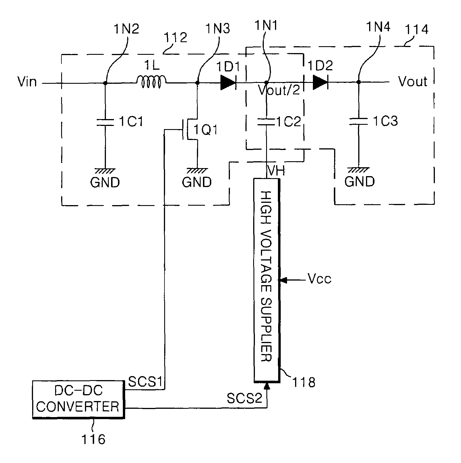
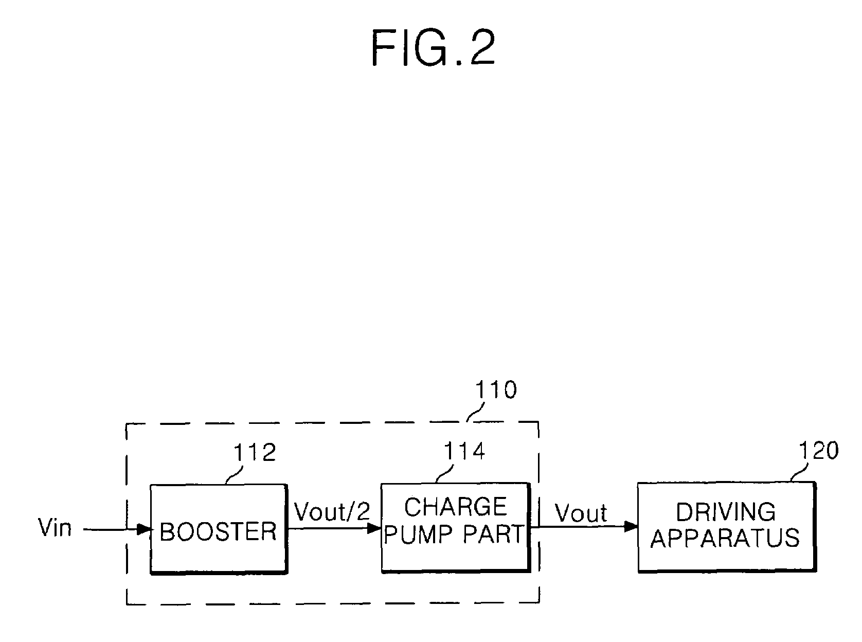
[0058]A DC-DC converter 110 according to the present invention, as shown in FIG. 3, includes a booster 112 to boost a DC voltage Vin supplied from an input line to half Vout / 2 of an output voltage Vout by use of a switching device 1Q1, a charge pump part 114 to convert the half Vout / 2 of the output voltage from the booster 112 into the output voltage Vout by a charge pumping method and supplied the converted output voltage Vout to a driving apparatus 120, a high voltage supplier 118 to supply high voltage VH to the charge pump part 114, and a DC-DC controller 116 to control the high voltage supplier 118 as well as controlling the switching action of the switching device 1Q1.

[0059]The DC-DC controller 116 generates a first switching control signal SCS1 to switch the switching device 1Q1, and in addition, generates a second switching control signal SCS2 to switch the high voltage supplier 118, which is synchronized with the first switching control signal SCS1.

[0060]The booster 112 inc...

second embodiment

[0076]Referring to FIGS. 5 and 6, a DC-DC converter 210 according to the present invention includes a charge pump part 214 to boost a DC voltage Vin supplied from an input line to half Vout / 2 of the output voltage Vout by use of a charge pumping method, a booster 212 to convert half Vout / 2 of an output voltage Vout from the charge pump part 214 by use of a switching device 2Q1, a low voltage supplier 218 to supply low voltage to the charge pump part 214, and a DC-DC controller 216 to control the low voltage supplier 218 as well as controlling the switching action of the switching device 2Q1.

[0077]The DC-DC controller 216 generates a first switching control signal SCS1 to switch the switching device 2Q1, and in addition, generates a second switching control signal SCS2 to switch the low voltage supplier 218, which is synchronized with the first switching control signal SCS2.

[0078]The low voltage supplier 218 supplies the low voltage VL inputted from a voltage source Vcc to a second c...


PUM


Abstract

The present invention relates to a power supply that is adaptive for improving energy conversion efficiency and a driving method thereof and an apparatus and method for driving an electroluminescence display device using the same. A power supply that supplies a driving power to drive a driving apparatus according to an embodiment of the present invention includes a power source to supply DC power; and a DC-DC converter to convert the DC power from the power source to a level of 1 / N (provided that N is a positive integer of not less than 2) times the driving power, and then to convert the converted DC power of 1 / N times to a level of the driving power.

Description

[0001]This application claims the benefit of the Korean Patent Application No. P2003-52979 filed on Jul. 31, 2003, which is hereby incorporated by reference.BACKGROUND OF THE INVENTION[0002]1. Field of the Invention[0003]The present invention relates to a power supply and a driving method thereof and an apparatus and method for driving an electroluminescence display device using the same, and more particularly to a power supply that is adaptive for improving energy conversion efficiency and a driving method thereof and an apparatus and method for driving an electroluminescence display device using the same.[0004]2. Description of the Related Art[0005]Recently, the application of a power supply becomes more activated in factory automation equipments, office automation equipments, information devices, communication devices and power system, wherein the power supply is stable and capable of enabling them to be made smaller and lighter.[0006]Generally, a switching power supply has two m...

Claims


Application Information

Patent Timeline
Patent Type & Authority Patents(United States)
IPC IPC(8): G09G3/30G09G3/20H01L51/50H05B44/00H02M3/07H02M3/155H02M3/156H05B33/14
CPCH02M3/07H02M3/156H02M2001/007H02M1/007G09G3/30
Inventor KIM, HYUN JEOUNGKIM, HAK SU
Owner LG ELECTRONICS INC
Why Eureka
Try Eureka